9
10
6
5
9
10
6
5
[11][12]
16
15
14
13
16
15
14
13
[13]
[14]
[a] [b] [c]
17
18
G
VDC/AC
DIN
kWh
W
1
2
3
45
67
89
10
11
12 13
14 15
16 17
18
S2 S1
CT1
P1 P2
S2 S1
CT2
P1 P2
N
N
L1
L1
L2
L3
L2L3
GND
serial
diagram
14
RS485
–+
Load
S2 S1
CT3
P1 P2
P1
LOAD
Current Transformer
P2
S1
S2
ENG
19
"Carel emeter" +0300044IE rel. 1.5 - 10.11.2017
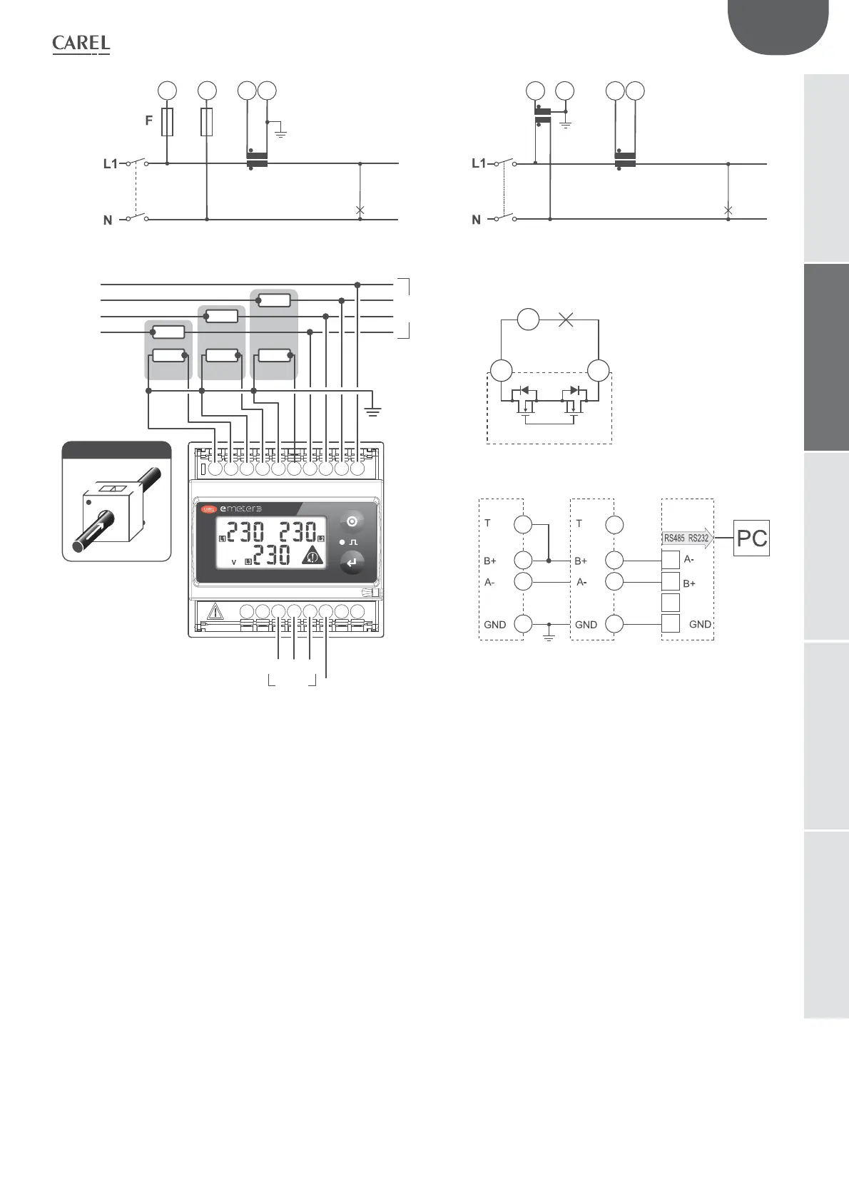
emeter3
Key:
System type selection 3P.n
[1] - 3-ph, 4-wire, unbalanced load, 3-CT connection
[2] - 3-ph, 4-wire, unbalanced load, 3-CT and 3-VT/PT connections
System type selection 3P
[3] - 3-ph, 3-wire, unbalanced load, 3-CT connection
[4] - 3-ph, 3-wire, unbalanced load, 3-CT and 3-VT/PT connections
[5] - 3-ph, 3
-wire, unbalanced load, 2-CT connnections (ARON)
[6] - 3-ph, 3-wire, unbalanced load, 3-VT/PT and 2-CT connections (ARON)
System type selection 3P.1
[7] - 3-ph, 3/4-wire, balanced load, 1-CT connection (if the neutral is available
the voltage connection can be realized to only 2-wire VL1 and
N)
[8] - 3-ph, 3-wire, balanced load, 1-CT and 3-VT/PT connection
System type selection 2P
[9] - 2-ph, 3-wire, 2-CT connection
[10] - 2-ph, 3-wire, 2-CT and 2-VT/PT connections
System type selection 1P
[11] - 1-ph, 2-wire, 1-CT connection.
[12] - 1-ph, 2-wire, 1-CT and
1-VT/PT connection
Static output and serial port
[13] - Opto-mosfet static output
[14] - RS485 connection 2 wires
[a] - last instrument
[b] - instrument 1...n,
[c]- RS485/RS232 transducer
(*) NOTE: For a correct power supply of the instrument, the neutral must always be connected