NO 1
COM 1
4231
GND
V REF
S1
S2
S3
S4
DI1
DI2
Analog – Digital Input Network
GND Tx/Rx
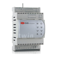
EVD evolution
twin
Fig. 3.a
Key:
LED On O Flashing
NET Connection active No
connection
Communication error
OPEN A/B Opening valve A/B - Driver A/B disabled (*)
CLOSE A/B Closing valve A/B - Driver A/B disabled (*)
OPEN B/
CLOSE B
- - EVD Evolution TWIN
operating as single
driver
A
/
B
Active alarm driver A/B - -
Controller powered Controller o Wrong power supply
(see chap. on Alarms)
Tab. 3.a
(*) Awaiting completion of the initial conguration
3.1 Assembling the display board (accessory)
The display board, once installed, is used to perform all the conguration and
programming operations on the two drivers. It displays the operating status,
the signicant values for the type of control that the drivers are performing
(e.g. superheat control), the alarms, the status of the digital inputs and the
relay outputs. Finally, it can save the conguration parameters for one
controller and transfer them to a second controller (see the procedure for
uploading and downloading the parameters).
For installation:
• remove the cover, pressing on the fastening points;
• t the display board, as shown;
• the display will come on, and if the controller is being commissioned, the
guided conguration procedure will start.
press
press
Fig. 3.b
Important: the controller is not activated if the conguration
procedure has not been completed.
The front panel now holds the display and the keypad, made up of 6 buttons,
that, pressed alone or in combination, are used to perform all the conguration
and programming operations on the controller.
3.2 Display and keypad
The graphic display shows two variables for each driver (A, B), the control
status of the driver, activation of the protectors, any alarms and the status of
the relay output.
Surriscaldam.
4.9 K
Apertura
valvola
44 %
ON
MOP
ALARM
-- Rele
1
2
3
4
5
7
A/B
6
T
8
Fig. 3.c
Key:
1 variable 1 on the display (driver A/B)
2 variable 2 on the display (driver A/B)
3 relay status (driver A/B)
4 alarm (press “HELP”)
5 protector activated
6 control status
7 current display: driver A/driver B
8 adaptive control in progress
Messages on the display
Control status Active protection
ON Operation LowSH Low superheat
OFF Standby LOP Low evaporation
temperature
POS Positioning MOP High evaporation
temperature
WAIT Wait HiTcond High condensing
temperature
CLOSE Closing
INIT Valve motor error recognition
procedure (*)
TUN Tuning in progress
Tab. 3.b
(*) The valve motor error recognition procedure can be disabled. See
paragraph 9.5.
(**) Only if EVD Evolution TWIN is operating as a single driver or programmable
superheat control is enabled.
Keypad
Button Function
Prg • opens the screen for entering the password to access
programming mode.
• if in alarm status, displays the alarm queue;
• in the “Manufacturer” level, when scrolling the parameters,
shows the explanation screens (Help);
• pressed together with ENTER, switches the display from one
driver to the other
Esc
• exits the Programming (Service/Manufacturer) and Display
modes;
• after setting a parameter, exits without saving the changes.
UP/DOWN
• navigates the screens on the display;
• increases/decreases the value.
ENTER
• switches from display to parameter programming mode;
• conrms the value and returns to the list of parameters;
• pressed together with HELP, switches the display from one
driver to the other.
Tab. 3.c
Note: :the variables displayed as standard can be selected by
conguring the parameters “Variable 1 on display” and “Variable 2 on display”
for each driver. See the list of parameters.

 Loading...