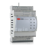
G0
G
E
X
V connection A
Power S upply
Relay A
NO A1
COM A
4231
GND
V REF
S1
S2
S3
S4
DI1
DI2
Analog – D igital Input Network
GND
Tx/Rx
EVD evolution
E
X
V connection B
Relay B
NO B
COM B
4231
aa
twin
b
Fig. 2.b
Terminal Description
G,G0 Power supply
VBAT Emergency power supply
Functional earth
1,3,2,4: ExV
connection A
Stepper motor power supply driver A
COM A, NO A Alarm relay driver A
1,3,2,4: ExV
connection B
Stepper motor power supply driver B
COM B, NO B Alarm relay driver B
GND Signal ground
VREF Power supply to active probes
S1 Probe 1 (pressure) or 4 to 20mA external signal
S2 Probe 2 (temperature) or 0 to 10 V external signal
S3 Probe 3 (pressure) or 4 to 20mA external signal
S4 Probe 4 (temperature)
DI1 Digital input 1
DI2 Digital input 2
Terminal for tLAN, pLan, RS485/ModBus® connection
Terminal for tLAN, pLan, RS485/ModBus® connection
Terminal for pLan, RS485/ModBus® connection
aa service serial port (remove the cover for access)
b serial port
Tab. 2.a
2.3 Connection diagram - superheat control
G
G0
G
G0
VBAT
COMA
NOA
1
3
24
NET
Tx/RxGND
DI1
S4
S3
S2
S1
GND
DI2
VREF
2 AT
24 Vac
230 Vac
35 VA
shield
EVD4
PC
EVD4 service USB adapter
EEV driver
4
S
EVDCNV00E0
Analog - Digital Input Network
OPEN A
CLOSE A
OPEN B
CLOSE B
A
B
COMB
NOB
1
3
24
A
shield
TRADRFE240
4
1
2
3
8
9
10
11
12
6
13
14
7
15
16
5
S
B
17
18
CAREL E
X
V
VALVE B
CAREL E
X
V
VALVE A
EVD evolution
twin
Fig. 2.c
Key:
1 green
2 yellow
3brown
4 white
5 personal computer for conguration
6 USB/tLAN converter
7 ratiometric pressure transducer–evaporation pressure driver A
8 NTC – suction temperature driver A
9 ratiometric pressure transducer–evaporation pressure driver B
10 NTC – suction temperature driver B
11 digital input 1 congured to enable control driver A
12 digital input 2 congured to enable control driver B
13 voltage-free contact driver A (up to 230 V)
14 solenoid valve A
15 alarm signal A
16 voltage-free contact driver B (up to 230 V)
17 solenoid valve B
18 alarm signal B
Note:
• connect the valve cable shield to the electrical panel earth;
• the use of driver A for superheat control requires the use of the evaporation
pressure probe S1 and the suction temperature probe S2, which will be
tted after the evaporator, and digital input 1 to enable control. As an
alternative to digital input 1, control can be enabled via remote signal
(tLAN, pLAN, RS485/ModBus®). For the positioning of the probes relating to
other applications, see the chapter on “Control”;
• the use of driver B for superheat control requires the use of the evaporation
pressure probe S3 and the suction temperature probe S4, which will be
tted after the evaporator, and digital input 2 to enable control. As an
alternative to digital input 2, control can be enabled via remote signal
(tLAN, pLAN, RS485/ModBus®). For the positioning of the probes relating to
other applications, see the chapter on “Control”;
• inputs S1, S2, S3 & S4 are programmable and the connection to the
terminals depends on the setting of the parameters. See the chapters on
“Commissioning” and “Functions”;

 Loading...