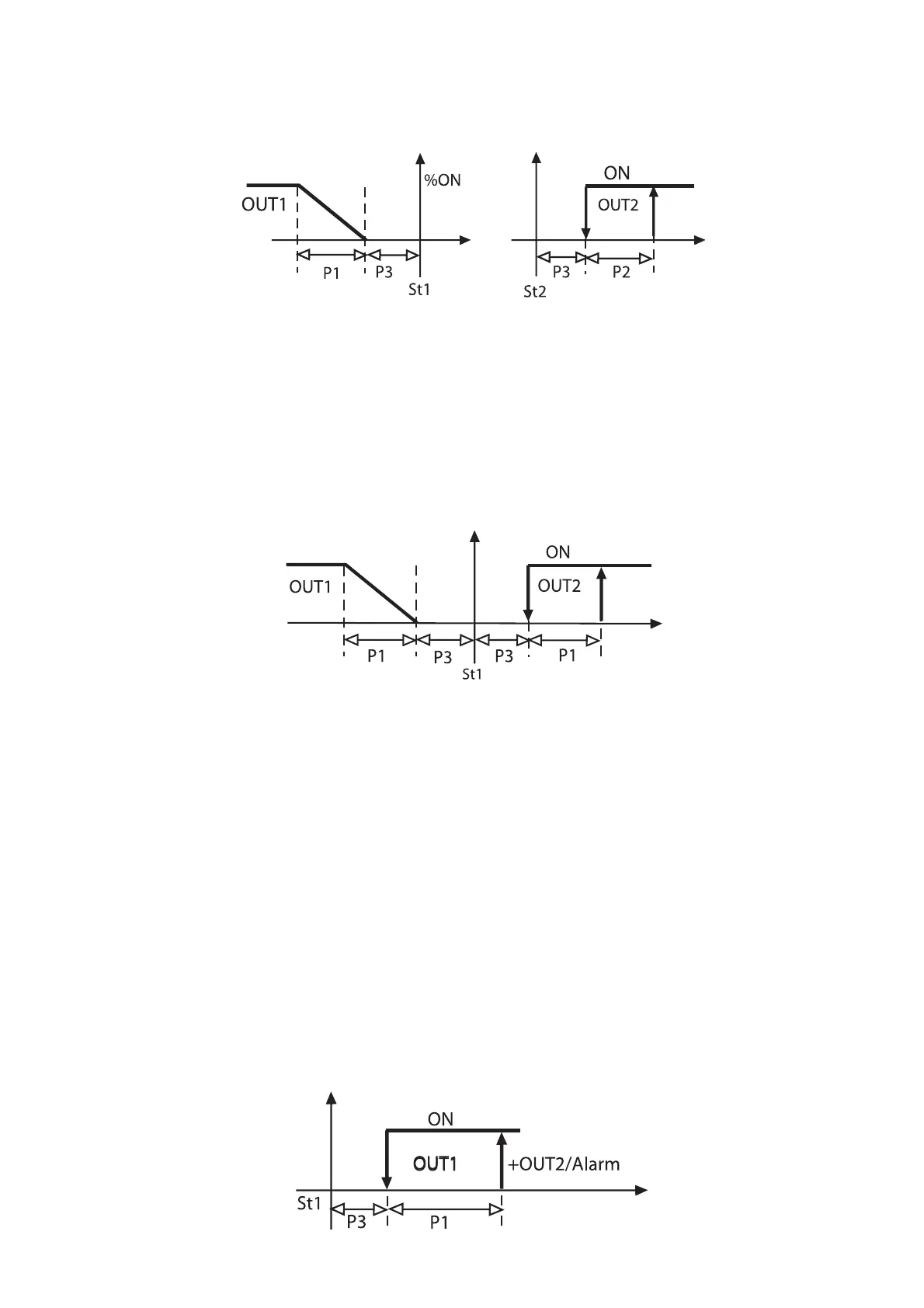
Nota: nel Modo 3 se si pone C33=1, l’uscita 1 continua a riferirsi
a St1 (e P1), mentre l’uscita 2 si riferisce a St2 (e P2) che è ora
impostabile distintamente.
Il disegno a fianco raffigura la nuova logica.
Da notare che:
1- La stessa funzionalità si sarebbe ottenuta partendo da Modo
4, modificando “TIPO DI USCITA di OUT2”=C39 da 1 a 0, in modo
che l’OUT2 diventasse da “tipo” PWM a “tipo” ON/OFF.
2- Nel caso si voglia mantenere un unico set point di regola-
zione si devono mantenere le due uscite dipendenti da St1.
Riprendendo l’esempio precedente basta porre DIPENDENZA di
OUT2=C38 =1. La figura 33 mostra il nuovo diagramma di rego-
lazione (si noti che i differenziali di lavoro per OUT1 e per OUT2
fanno riferimento entrambi a P1).
Esempio 15
Si vuole gestire in una cella il comando compressore ed avere
una uscita di allarme.
Soluzione 1: si può utilizzare un regolatore a 2 uscite nel Modo
5: di fabbrica OUT2 gestisce l’allarme ed OUT1 una logica di
comando Reverse. Sarà sufficiente modificare la logica di OUT1
per soddisfare la richiesta. St1, P1 e P3 definiscono la regolazione
finale.
Modo di partenza: C0=5 salvare la modifica uscendo dalla pro-
grammazione e rientrare in programmazione, con Passwod 77,
ponendo C33=1.
OUT1: uscita ON/OFF che deve passare da logica Reverse a logi-
ca Direct.
INSERZIONE = C36 passa da -100 a +100
DIFFERENZIALE/LOGICA = C37 passa da +100 a -100
(DIPENDENZA e TIPO DI USCITA invariati).
OUT2: già uscita di allarme, restano invariati i parametri.
I parametri P25, P26, P27 e P28 completeranno la programmazio-
ne di allarme temperatura.
In figura 44 è rappresentata la logica ottenuta.
Note: when working in Mode 3, setting C33=1 implies that the
first output will be directly related to St1 (and P1) whilst output 2 will
be related to St2 (and P2) whose value can be directly selected.
The graph below illustrates the new operating logic.
Please note that:
1- the same regulation logic might be achieved starting from
Mode 4 and modifying the TYPE OF OUTPUT relative to OUT2 as
follows: TYPE OF OUTPUT=C39=0, (setting 0 instead of 1 causes
the output to work in the ON/OFF instead of the PWM logic).
2- if you want to maintain only one set-point, the two outputs
must be related to St1. Set Dependence of Out2=C38=1. Fig. 33
shows the new control graph (differentials for OUT1 and OUT2
refer to P1).
Example no. 15:
Control of a single-compressor cold storage room with one
alarm output.
Solution 1: use a two-output controller and set Mode 5 so that
OUT2 will manage the alarm and OUT1 the REVERSE mode. To
meet the above application requirement, all you have to do is
modify the control logic of OUT1.
Starting Mode: C0=5; confirm the variation by exiting the pro-
gramming field, then enter again (password 77) and set C33=1.
OUT1: ON/OFF output, from Reverse to Direct mode
ENERGIZATION = C36 changes from -100 to +100
DIFFERENTIAL/LOGIC = C37 changes from +100 to -100
(Dependence and Differential/Logic unchanged)
OUT2: used as alarm output (parameters remain unchanged).
P25, P26, P27 and P28 allow you to complete the programming
step by setting the temperature alarms.
The graph below (fig. 44) shows the new control logic:
55
Fig.42
Fig.43
Fig.44

 Loading...


