Le modifiche da apportare sono:
Modo di partenza: C0=2
ingresso digitale 1: gestione allarme con blocco uscite e
attivazione uscita di allarme.
C29=2 allarme immediato con Reset manuale;
C31=0 in caso di allarme da ingresso digitale tutte le uscite ven-
gono spente.
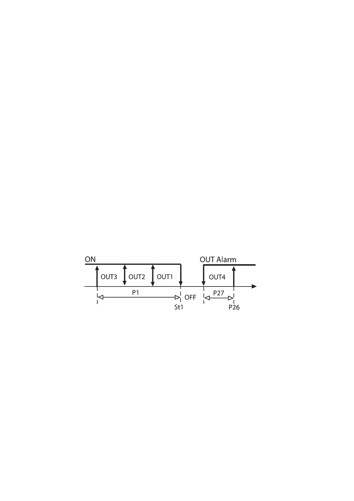
OUT1:
uscita ON/OFF per comando del primo bruciatore:
INSERZIONE=C36=-33 DIFFERENZIALE/LOGICA=C37=33
(DIPENDENZA e TIPO DI USCITA invariati)
OUT2:
uscita ON/OFF per comando del secondo bruciatore:
INSERZIONE=C40=-66 DIFFERENZIALE/LOGICA=C41=33
(DIPENDENZA e TIPO DI USCITA invariati)
OUT3:
uscita ON/OFF per comando del terzo bruciatore:
INSERZIONE=C44=-100 DIFFERENZIALE/LOGICA=C45=34
(DIPENDENZA e TIPO DI USCITA invariati)
OUT4:
uscita ON/OFF d’allarme di “Alta” e da blocco esterno.
DIPENDENZA C46=5 (o 6 se si preferisce il relè normalmente eccitato)
P26 = livello di “Alta” temperatura richiesto (Es. 90°C)
P27 = differenziale allarme (visto che l’allarme deve essere
assoluto, P27 deve essere positivo)
P28 = eventuale ritardo allarme temperatura e blocco
Il grafico raffigura la logica di funzionamento selezionata.
Esempio 14
In un impianto di stagionatura si controlli la temperatura tramite
un compressore (generatore di freddo) ed una resistenza elet-
trica (generatore di calore). Il controllo deve agire con una zona
neutra di 3 °C attorno ad un set di 5 °C.
Il comando della resistenza dovrà essere di tipo PWM per un
inserimento proporzionale della potenza.
Soluzione: Modo di partenza: C0=3 salvare la modifica uscendo
dalla programmazione con PRG, rientrare in programmazione,
P.W.77, ponendo C33=1;
St1=5°C – P3=1,5°C P1 e P2 stabiliranno il differenziale di lavoro
rispettivamente della resistenza e del compressore.
OUT1: comando della resistenza con funzionamento PWM;
TIPO DI USCITA=C35=1, per funzionamento PWM (DIPENDENZA,
INSERZIONE e DIFFERENZIALE/LOGICA invariati).
OUT2: uscita ON/OFF per comando del compressore: resta
invariata.
In short:
Starting Mode: C0=2;
Digital input no.1: alarm management with output disenergiza-
tion and energization of the alarm output;
C29=2: immediate alarm, manual reset;
C31=0: in the event of off-normal condition, all outputs will
disenergise;
OUT1:
ON/OFF output to control the first burner unit
ENERGIZATION=C36=-33 DIFFERENTIAL/LOGIC=C37= 33
(Dependence and Type of Output remain unchanged).
OUT2:
ON/OFF output to control the second burner unit
ENERGIZATION=C40=-66 DIFFERENTIAL/LOGIC=C41= 33
(Dependence and Type of Output remain unchanged).
OUT3:
ON/OFF output to control the third burner unit
ENERGIZATION=C44=-100 DIFFERENTIAL/LOGIC=C45=
34(Dependence and Type of Output remain unchanged).
OUT4:
ON/OFF output for high temperature alarm and external system lock.
DEPENDENCE C46=5 (or 6 if you prefer a normally energized relay);
P26=sets the required high temperature level (e.g. 90°C);
P27=alarm differential (P27 must be a positive value);
P28=time-delay (if any) before the activation of the temperature/
system lock alarm.
The graph below illustrates the new control logic:
Example no. 14
Control and regulation of the temperature of a cold storage
room by means of a compressor (cooling function) and an elec-
tric heater (heating function). The controller will develop correc-
tive action in response to deviation from the desired conditions,
according to the set values, that is neutral zone=3°C and set-
point=5°C. The heater operates in the PWM logic so as to obtain a
proportional operating logic.
Solution: Starting Mode: C0=3: Confirm the modification by
exiting the programming field through PRG, then enter again
(password 77) and set C33=1; St1=5°C – P3=1.5°C
P1 and P2 represent the operating differential of heater and
compressor respectively.
OUT1: Control of the heater, PWM logic; TYPE OF
OUTPUT=C35=1, PWM function (DEPENDENCE, ENERGIZATION
and DIFFERENTIAL/LOGIC remain unchanged).
OUT2: ON/OFF output for the control of the compressor
(unchanged)
54
Fig.41

 Loading...


