OUT1: deve essere programmata come uscita di allarme attiva solo
in caso di allarme di “Bassa”. Si deve quindi modificare la dipendenza
DIPENDENZA=C34 che passa da 1 a 9 (o 10 se si vuole lavorare con
relè normalmente ON). I parametri C35, C36, C37 non hanno più
rilevanza e restano invariati.
OUT2: si svincolerà dal funzionamento DIFFERENZIALE cam-
biando la DIPENDENZA da 1 a 2: quindi DIPENDENZA=C38=2.
La logica è di tipo Direct e comprende tutto P2, quindi
INSERZIONE=C40 diventa 100, e DIFFERENZIALE/LOGICA=C41
diventa -100. St2 sarà ovviamente impostato a 8 e P2 rappresen-
ta la variazione minima necessaria per riavviare l’unità, una volta
che si è arrestata per “Bassa” temperatura, es P2=4.
OUT3 e OUT4: negli strumenti con 4 uscite, il Modo 1 assegna
ad ogni uscita una isteresi pari al 25% del differenziale P1. Nell’esempio
considerato le uscite effettivamente utilizzate per la regolazione sono
2, per cui si vuole che l’isteresi di ogni uscita sia il 50% di P1. È neces-
sario quindi cambiare i parametri INSERZIONE e DIFFERENZIALE/
LOGICA delle uscite indicate in modo che si adattino alla nuova
situazione.
In pratica si dovrà porre:
OUT3:
INSERZIONE=C44 passa da 75 a 50
DIFFERENZIALE/LOGICA=C45, passa da -25 a -50.
OUT4:
INSERZIONE=C48 resta a 100
DIFFERENZIALE/LOGICA = C49 passa da -25 a -50.
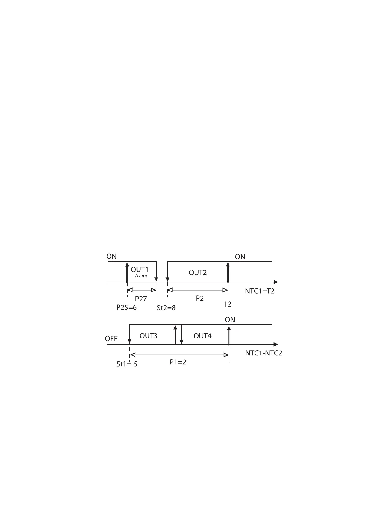
Il disegno riassume la logica di funzionamento della
regolazione:
Esempio 13
Si vuole pilotare 3 bruciatori di una caldaia per portare l’acqua
alla temperatura St1. È richiesta un’uscita di allarme che deve
essere attivata nel caso in cui l’acqua superi un limite di “Alta”
temperatura o in caso sia segnalato un blocco dell’impianto.
Soluzione: supposto che il segnale di blocco sia disponibile
come contatto pulito, si potrà utilizzare l’ingresso digitale per la
sua gestione. Si dovrà poi configurare un’uscita come allarme
(DIPENDENZA=5 o 6).
Il Modo di partenza può essere lo standard, ovvero C0=2.
OUT1: program it as active alarm output to be used in the event
of low temperature alarm; in this case modify dependence
(DEPENDENCE=C34) from 1 to 9 (or 10 if you want normally
open relays). You do not need to modify C35, C36, C37.
OUT2: in order to make idle the DIFFERENTIAL function, change
DEPENDENCE from 1 to 2: DEPENDENCE=C38=2. The controller
will perform in the DIRECT logic and will include the entire value
of P2: Therefore old ENERGIZATION= C40 becomes C40=100, and
old DIFFERENTIAL/LOGIC=C41 becomes C41=-100. Set St2=8. P2
indicates the minimum variation necessary to re-start the unit
following a low temperature condition (e.g. P2=4).
OUT3 and OUT4: when using 4-output controllers, setting Mode
1 means to give each output a hysteresis corresponding to 25% of
the differential P1. In the example shown below, there are 2 actual
control outputs (OUT3 and OUT4) so the hysteresis of each output
should correspond to 50% of P1. It is therefore necessary to chan-
ge ENERGIZATION and DIFFERENTIAL/LOGIC referrring to the indi-
cated output so as to meet the new application requirements.
In short:
OUT3:
ENERGIZATION=C44 changes from 75 to 50
DIFFERENTIAL/LOGIC=C45 changes from -25 to -50.
OUT4:
ENERGIZATION=C48 remains 100
DIFFERENTIAL/LOGIC=C49 changes from -25 to -50.
The graph below shows the new control logic:
Example no. 13
Control and regulation of 3 boiler burner units so as to bring
the water temperature to St1. You need one alarm output that
will energise in the event the water temperature rises above the
“High” temperature threshold or in the event the system locks.
Solution: Use the digital input (voltage-free contact) to regulate
the ‘system lock’ signal. Then configure another output as alarm
output (DEPENDENCE=5 or 6).
As for the Mode, there is no need to change its standard setting,
that is C0=2.
53
Fig.40

 Loading...


