14
ENG
ir33 universale +030220801 - rel. 1.0 - 16.04.2008
2.6 Installation
To install the controller, proceed as follows, with reference to the wiring
diagrams:
1) connect the probes and power supply: the probes can be installed
up to a maximum distance of 100 m from the controller, using
shielded cables with a minimum cross-section of 1 mm. To improve
immunity to disturbance, use probes with shielded cables (connect
only one end of the shield to the earth on the electrical panel).
2) Program the controller: see the chapter “User interface”.
3) Connect the actuators: the actuators should only be connected
after having programmed the controller. Carefully check the
maximum relay capacities, indicated in “technical speci cations”.
4) Serial network connection: if connection to the supervisor
network is available using the relevant serial cards (IROPZ485*0 for
IR33 & IROPZSER30 for DN33), make sure the system is earthed.
Speci cally, the secondary of the transformers that
supply the controllers must not be earthed. If connection to a
transformer with earthed secondary winding is required, an
insulating transformer must be installed in between. A series of
controllers can be connected to the same insulating transformer,
nevertheless it is recommended to use a separate insulating
transformer for each controller.
Avoid installing the controller in environments with the following
characteristics:
relative humidity over 90% non-condensing;
•
heavy vibrations or knocks;•
exposure to continuous jets of water;•
exposure to aggressive and polluting atmospheric agents (e.g.: sulphur •
and ammonia gases, saline mist, smoke) which may cause corrosion
and/or oxidation;
high magnetic and/or radio frequency interference (e.g. do not installe •
near transmitting antennas);
exposure to direct sunlight and atmospheric agents in general.•
The following warnings must be observed when connecting the
controllers:
incorrect connection of the power supply may seriously damage the •
system;
use cable ends that are suitable for the terminals. Loosen every screw •
and t the cable end, next tighten the screws and gently pull the
cables to check their tightness;
separate as much as possible (at least 3 cm) the probe and digital •
input cables from inductive loads and power cables, to avoid any
electromagnetic disturbance. Never lay power and probe cables in the
same cable conduits (including those for the electrical panels);
do not install the probe cables in the immediate vicinity of power •
devices (contactors, circuit breakers or the like). Reduce the length of
the sensor cables as much as possible, and avoid spirals around power
devices;
avoid supplying the controller directly from the main panel power •
supply if also supplying power to other devices, such as contactors,
solenoid valves, etc., which require another transformer.
2.7 Programming key (copy set-up)
The keys must be connected to the connector (4 pin AMP) tted on the
controllers. All the operations can be performed with the controller o .
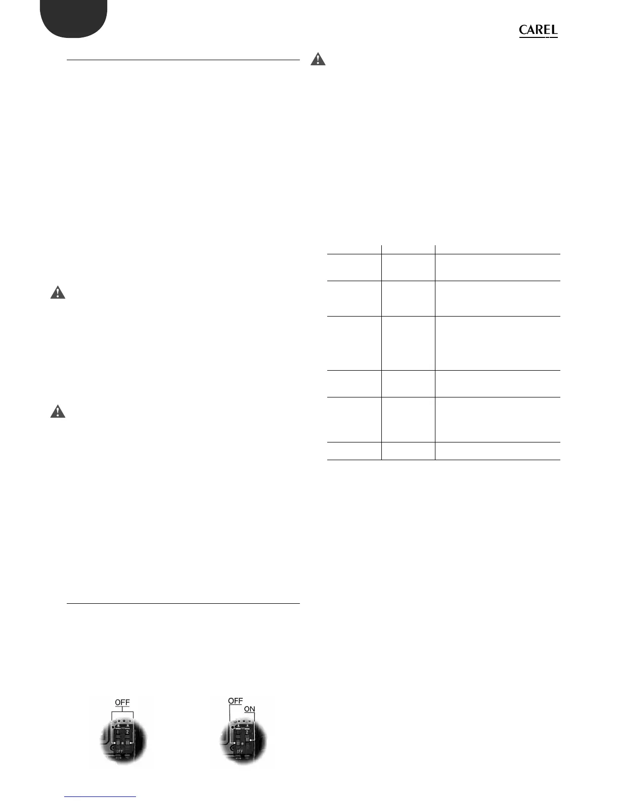
The functions are selected using the 2 dipswitches, accessed by removing
the battery cover:
load the parameters for a controller onto the key (UPLOAD - Fig. 1);•
copy from the key to a controller (DOWNLOAD - Fig. 2);•
UPLOAD DOWNLOAD
The parameters can only be copied between controllers with the same
code. The UPLOAD operation can, however, always be performed.
2.7.1 Copying and downloading the parameters
The following operations are used for the UPLOAD and/or DOWNLOAD
functions, simply by changing the settings of the dipswitches on the
key:
1. open the rear cover on the key and position the 2 dipswitches
according to the desired operation;
2. close the rear cover on the key and plug the key into the connector
on the controller;
3. press the button and check the LED: red for a few seconds, then
green, indicates that the operation was completed correctly.
Other signals or the ashing of the LED indicates that problems
have occurred: refer to the table;
4. at the end of the operation, release the button, after a few seconds
the LED goes OFF;
5. remove the key from the controller.
LED signal Error Meaning and solution
Red LED ashing Batteries
discharged at
start copy
The batteries are discharged, the copy
operation cannot be performed. Replace
the batteries.
Green LED
ashing
Batteries
discharged
during copy or
at end of copy
During the copy operation or at the end
of the operation the battery level is low.
Replace the batteries and repeat the
operation.
Red/green LED
ashing
(orange signal)
Instrument not
compatible
The parameter set-up cannot be copied
as the connected controller model is not
compatible. This error only occurs for the
DOWNLOAD function; check the code of
the controller and run the copy only for
compatible codes.
Red and green
LED on
Error in data
being copied
Error in the data being copied. The data
saved on the key are partly/completely
corrupted. Reprogram the key.
Red LED on
steady
Data transfer
error
The copy operation was not completed
due to a serious error when transferring
or copying the data. Repeat the
operation, if the problem persists check
the key connections.
LEDs o Batteries
disconnected
Check the batteries.
 Loading...


