23
ON
OUT1
Mod. V
OFF
St1
B1P1
ON
OUT1 OUT2
Mod. W
OFF
St1
B1
P1
ON
OUT1 OUT2 OUT3 OUT4
Mod. Z
OFF
St1
B1
P1
ENG
ir33 universale +030220801 - rel. 1.0 - 16.04.2008
5.1 Probes (analogue inputs)
The probe parameters are used to :
set the type of probe
•
set the o set to correct the probe reading (calibration)•
activate a lter to stabilise the reading•
set the unit of measure shown on the display•
enable the second probe and the compensation function•
Par. Description Def Min Max UoM
c13 Type of probe
0=NTC standard range (-50T+90°C)
1=NTC enhanced range(-40T+150°C)
2=PTC standard range(-50T+150°C)
3=PT100 standard range(-50T+150°C)
00 3 -
P14 Calibration of probe 1 0 -20 20 °C/°F
P15 Calibration of probe 2 0 -20 20 °C/°F
c17 Probe disturbance lter 4 1 15 -
c18 Select temperature unit of measure
0=°C
1=°F
00 1 -
Parameter c13 de nes the type of probe 1 (B1) and any probe 2 (B2).
Parameters P14 and P15, for probe 1 and probe 2 respectively, are used to
correct the temperature measured by the probes indicated on the display,
using an o set: the value assigned to these parameters is in fact added
to (positive value) or subtracted from (negative value) the temperature
measured by the probes. When pressing Set, after having entered the
value, the display does not show the parameter, but rather immediately
shows the new value of the probe reading being calibrated. This means
the result of the setting can be checked immediately and any adjustments
made as a consequence. Press Set again to access the parameter code
and save the value. Parameter c17 de nes the coe cient used to stabilise
the temperature reading. Low values assigned to this parameter allow a
prompt response of the sensor to temperature variations, but the reading
becomes more sensitive to disturbance. High values slow down the
response, but guarantee greater immunity to disturbance, that is, a more
stable and more precise reading.
5.1.1 Second probe (parameter c19)
Par. Description Def Min Max UoM
c19 Operation of probe 2
0=not enabled
1=di erential operation
2=compensation in cooling
3=compensation in heating
4=compensation always active
5=enable logic on absolute set point
6=enable logic on di . set point
Validity : c0=1 or 2
006-
The second probe must be the same type as the rst, NTC, NTC-HT, PTC or
PT1000, as set by parameter c13.
For the explanation of the types of control based on parameter c19, see
the chapter on “Control”.
5.2 Standard operating modes (parameters
St1,St2,c0,P1,P2,P3)
The controller can operate in 9 di erent modes, selected by parameter
c0. The basic modes are “direct” and “reverse”. In “direct” mode, the output
is activated if the value measured is greater than the set point plus a
di erential. In “reverse” mode the output is activated if the temperature is
less than the set point plus a di erential. The other modes are a combination
of these, with possibility of 2 set points (St1 & St2) and 2 di erentials (P1 &
P2) based on the mode, “direct” or “reverse”, or the status of digital input
1. Other modes include “dead zone” (P3), “PWM” and “alarm”. The number
of outputs activated depends on the model (V/W/Z=1,2,4 relay outputs,
D/A =1/4 PWM outputs, B/E=1/2 analogue outputs and 1/2 relay outputs).
Selecting the correct operating mode is the rst action to be performed
when the default con guration, i.e. “reverse” operation, is not suitable for
the application in question.
Par. Description Def Min Max UoM
St1 Set point 1 20 c21 c22 °C/°F
St2 Set point 2 40 c23 c24 °C/°F
c0 1=direct
2=reverse
3=dead zone
4=PWM
5=alarm
6=direct/reverse from digital input 1
7=direct: set point & di erential from
digital input 1
8=reverse: set point & di erential from
digital input 1
9=direct & reverse with separate set p.
21 9 -
P1 Set point di erential 1 2 0.1 50 °C/°F
P2 Set point di erential 2 2 0.1 50 °C/°F
P3 Dead zone di erential 2 0 20 °C/°F
c21 Minimum value of set point 1 -50 -50 c22 °C/°F
c22 Maximum value of set point 1 60 c21 150 °C/°F
c23 Minimum value of set point 2 -50 -50 c24 °C/°F
c24 Maximum value of set point 2 60 c23 150 °C/°F
To be able to set c0, the value of c33 must be 0. If c33=1, changing c0
has no e ect.
For the mode set to become immediately operational, the controller
needs to be switched o an on again. Otherwise correct operation is not
guaranteed.
The meaning of parameters P1 & P2 changes according to the operating
mode selected. Fore example, in modes 1 & 2 the di erential is always
P1. P2, on the other hand, is the “reverse” di erential in mode 6 and the
“direct” di erential in mode 9.
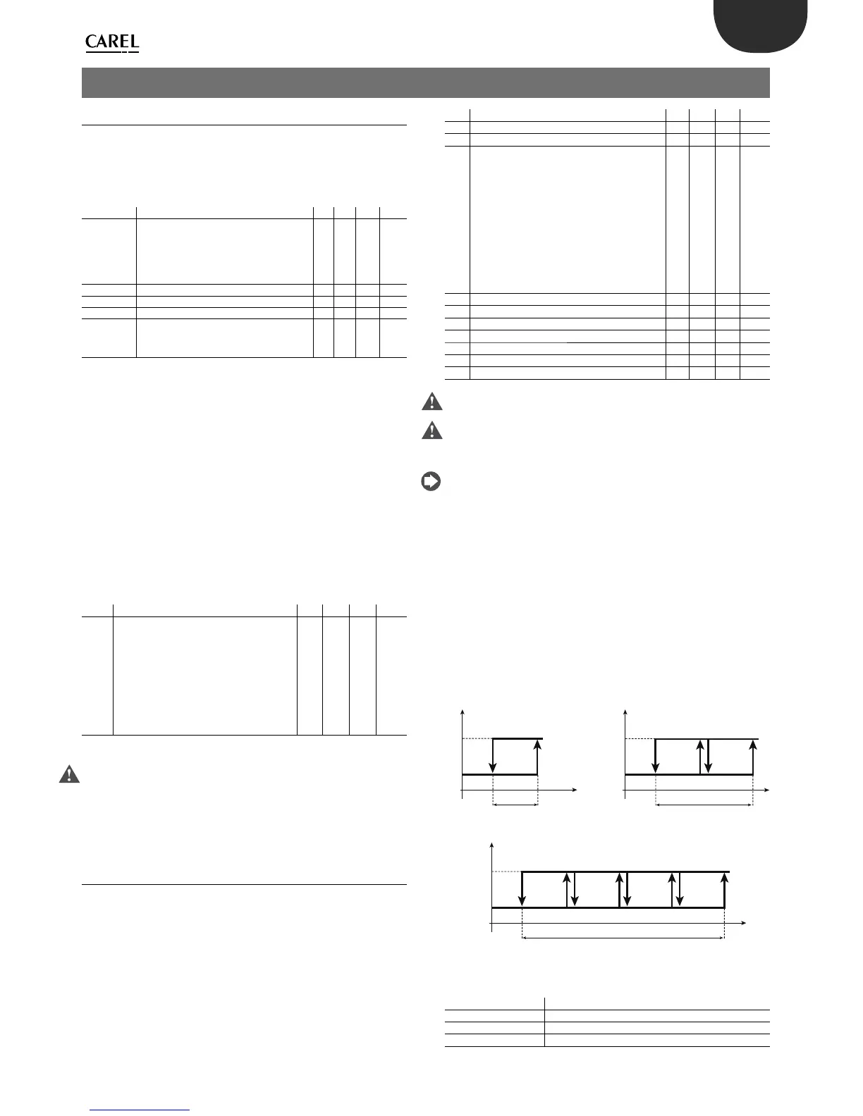
5.2.1 Direct (parameter c0=1)
In “direct” operation the controller ensures the value being controlled (in
this case the temperature) does not exceed the set point (St1). If it does,
the outputs are activated in sequence. The activation of the outputs is
distributed equally across the di erential (P1). When the value measured
is greater than or equal to St1+P1 (in proportional only operation), all the
outputs are activated. Similarly, if the value measured starts falling, the
outputs are deactivated in sequence. When reaching St1, all the outputs
are deactivated.
Key
St1 Set point 1
P1 Set point di erential 1
OUT1/2/3/4 Output 1/2/3/4
B1 Probe 1
5. FUNCTIONS
 Loading...


