26
St1 St2
St1 St2
OUT1 OUT2
Mod. W
B1P1
P2
OUT1OUT2 OUT4OUT3
ON
OFF
ON
OFF
Mod. Z
B1
P1 P2
ENG
ir33 universale +030220801 - rel. 1.0 - 16.04.2008
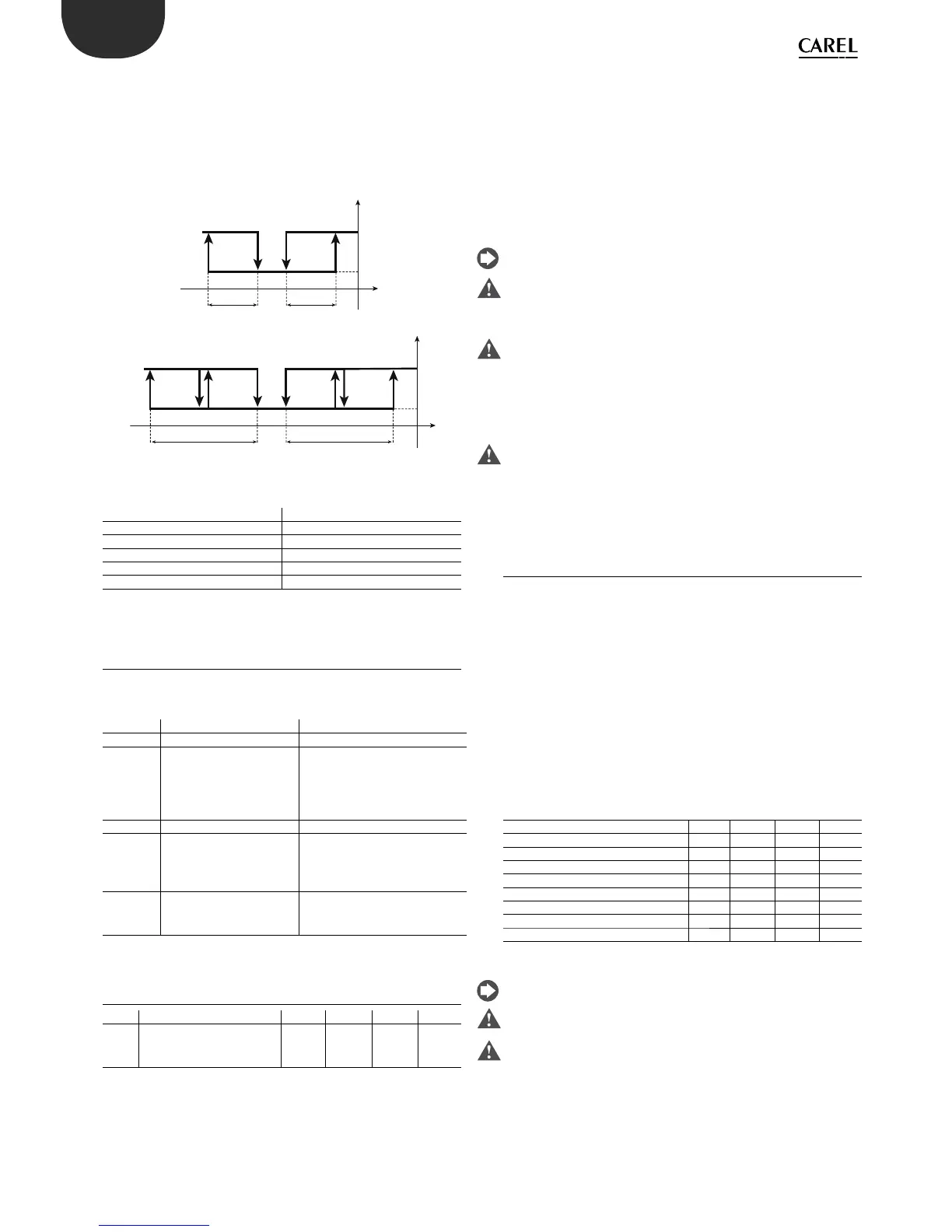
5.2.9 Direct/reverse with two set points (par. c0=9)
In this mode, available only on the models with 2 or 4 outputs, half of the
outputs are active in “direct” mode and half in “reverse”. The unique aspect
is that there are no restrictions in the setting of the set point for the two
actions, therefore it is like having two independent controllers that work
with the same probe.
Key
St1/St2 Set point 1/2
P1 “Reverse” di erential St1
P2 “Direct” di erential St2
OUT1/2/3/4 Output 1/2/3/4
B1 Probe 1
5.3 Validity of control parameters
(parameters St1,St2,P1,P2,P3)
The parameters that de ne the operating mode have the validity de ned
in the table below:
Parameter Validity Note
St1 All modes
St2 c0 = 6,7,8,9 or any value
of c0 if c33 = 1(special
operation). If c19=2,
3 or 4, St2 is used in
compensation
In special operation (c33=1),
St2 is shown in all modes but
is only active for outputs with
dependence equal to 2.
P1 All modes
P2 c0=3,4,5,6,7,8,9
Active also in other modes
if c33=1 (special operation)
or c19=4.
note that in modes 3, 4 and 5, P2
is the di erential of the “direct”
action and refers to St1.
P3 c0=3,4 & 5
When c0=5 models W &
Z only
5.4 Selecting the special operating mode
Par. Description Def Min Max UoM
c33
Special operation
0= Disabled
1= Enabled
00 1-
Parameter c33 o ers the possibility to create custom operating logic,
called special operation. The logic created may be a simple adjustment or
a complete overhaul of one of the nine modes. In any case, note that:
Modes 1, 2, 9: do not consider the dead zone P3 nor the changeover in
•
logic from digital input
Modes 3, 4, 5: enable the dead zone di erential P3. No changeover in •
logic from digital input.
Mode 6: does not consider the di erential P3. The changeover of •
digital input 1 means the outputs consider set point 2 rather than
set point 1. The direct/reverse logic will be inverted. For outputs with
“dependence”=2, only the changeover in logic is active, that is, the
closing of the digital contact maintains “dependence”=2 (St2) but
inverts the logic, exchanging the signs for “activation” and “di erential/
logic” (see the explanation below).
Modes 7, 8: do not consider the dead zone P3. For outputs with
•
“dependence”=1, the digital input only shifts the reference from St1/P1
to St2/P2, maintaining the control logic (“activation” “di erential/logic”
do not change sign). The digital input does not have any in uence on
the other control outputs, that is, with “dependence”=2 and alarms.
For the explanation of the “dependence”, “activation” and “di erential/
logic” parameters, see the following paragraphs.
Before selecting c33=1: for starting modes other than c0=2 (default), this
must be set before enabling special operation (c33=1): the change to c0
must be saved by pressing Prg/mute.
When c33=1, changing c0 no longer a ects the special parameters. That
is, c0 can be set however the special parameters (from c34 to d49) and
the typical functions remain frozen in the previous mode with c33=1:
while the parameters can be set individually, the typical functions cannot
be activated. In conclusion, only after having set and saved the starting
mode can the parameters be edited again and c33 set to 1.
If the mode needs to be changed after c33 has been set to 1, rst return
c33=0, press Prg/mute to con rm, set the required mode and save
the change (Prg/mute), then return to special operation with c33=1.
Setting c33 from 1 to 0, the controller cancels all changes to the “special
parameters”, which return to the values dictated by c0..
5.5 Special operating modes
When c33=1, 32 other parameters become available, the so-called special
parameters. The special parameters are used to completely de ne the
operation of each individual output available on the controller. In normal
operation, that is, choosing the operating mode using parameter “c0”,
these parameters are automatically set by the controller. When c33=1,
the user can adjust these settings using the 8 parameters that de ne
each individual output:
dependence•
type of output•
activation•
di erential/logic•
activation restriction•
deactivation restriction•
maximum/minimum modulating output value (PWM or 0-10Vdc)•
Special parameters and correspondence with the various outputs
OUT1 OUT2 OUT3 OUT4
Dependence c34 c38 c42 c46
Type of output c35 c39 c43 c47
Activation c36 c40 c44 c48
Di erential/logic c37 c41 c45 c49
Activation restriction d34 d38 d42 d46
Deactivation restriction d35 d39 d43 d47
Minimum modulating output value d36 d40 d44 d48
Maximum modulating output value d37 d41 d45 d49
For the default and minimum and maximum values of the special
parameters, see the table of parameters.
Before setting parameter c33, make sure the required starting mode –
param.c0 - has been set.
When c33=1, the special parameters are not visible and cannot be set
to achieve the required operation. Only the set point and the di erential
will be modi able.
 Loading...


