27
St1=10
c36=-100
St2=20
c40=+75
OUT1
AB
OUT2
B1
P1=6 P1=6 P2=6 P2=6
ON
OFF
ON
OUT1
OUT2
OFF
t
c12
TON_2
ON
OFF
c12
TON_1
ENG
ir33 universale +030220801 - rel. 1.0 - 16.04.2008
5.5.1 Dependence (parameters c34,c38,c42,c46)
This the parameter that determines the speci c function of each output.
It links an output to a set point (control output) or a speci c alarm (alarm
output). Parameters c34,c38,c42,c46 correspond respectively to outputs
1,2,3,4, and the selection eld ranges from 0 to 17.
Dependence = 0: the output is not enabled. This is the value set on
versions V and W for the outputs that are not available (that is 2, 3 & 4 for
version V, 3 & 4 for version W).
Dependence = 1 & 2: the output is the control output and refers to St1/
P1 and St2/P2 respectively. In the subsequent special parameters, “type
of output”, “activation” and “di erential/logic”, the operation of the output
can be de ned completely.
Dependence = 3 to 14: the output is associated with one or more alarms.
See the chapter on “Alarms” for the complete list.
Dependence = 15: “timer” operation. The output becomes independent
of the measurement, set points, di erentials, etc. and continues to switch
periodically at a period=c12 (cycle time). The ON time (T_ON) is de ned by
the “activation” parameter as a percentage of the set cycle time. If an alarm
occurs or the controller is switched OFF, “timer” operation is deactivated.
For further information, see the description of the parameters “type of
output”, “activation”.
Dependence = 16: the output is the control output: the association St1/
P1 and St2/P2 depends on the status of digital input 1. If the input is open,
reference will be to St1/P1; if the input is closed, reference will be to St2/
P2. Changing the set point also reverses the operating logic.Dependence
= 17: the output is the control output: the association St1/P1 and St2/P2
depends on the status of digital input 1. If the input is open, reference will
be to St1/P1; if the input is closed, reference will be to St2/P2. Changing
the set point maintains the operating logic.
DEPENDENCE
VALUE
OUTPUT ALARM RELAY
STATUS IN
NORMAL
CONDITIONS
0 not active -
1 relative to St1 -
2 relative to St2 -
3 active with alarm from digital input OFF
4 active with alarm from digital input ON
5 active with serious and “High” alarms E04) OFF
6 active with serious and “High” alarms (E04) ON
7 active with serious and “Low” alarms (E05) OFF
8 active with serious and “Low” alarms (E05) ON
9 active with “Low” alarm (E05) OFF
10 active with “Low” alarm (E05) ON
11 active with “High” alarm (E04) OFF
12 active with “High” alarm (E04) ON
13 active with serious alarm OFF
14 active with serious alarm ON
15 TIMER operation -
16 operation of the output dependent on the
status of digital input 1 with reversal of the
operating logic
-
17 operation of the output dependent on the
status of digital input 1 with operating logic
maintained
-
Alarm relay OFF =output normally deactivated; energised with alarm.
Alarm relay ON = output normally activated; de-energised with alarm.
When ON the relay is normally active: it is deactivated with an alarm.
This is an intrinsic safety feature, as the contact switches, and thus the
alarm is signalled, even if there is a power failure,
serious faults on the controller or a data memory alarm (E07/E08.)
In the models B and E, for the outputs 2 and 4, the dependence may be
only 0, 1, 2.
5.5.2 Type of output (parameters c35,c39,c43,c47)
The parameter is active only if the output is the control output
(“dependence”=1,2,16,17) or TIMER (“dependence”=15).
Type of output=0: the output is on/o .
Type of output=1: the output is PWM or “timer”.
“Timer” operation is combined with “dependence”=15.
In the models B and E, the output type will always be 0 to 10 Vdc
independently from the value of this parameter.
5.5.3 Activation (parameters c36,c40,c44,c48)
The parameter is active only if the output is the control output
(“dependence”=1,2,16,17) or TIMER (“dependence”=15).
If “dependence”=1, 2, 16 and 17 it represents, for ON/OFF operation, the
activation point of the output while, for PWM operation, it indicates the
point where the output has the maximum value. The “activation” parameter
is expressed as a percentage, from -100 to +100 and refers to the operating
di erential and the set point that the output refers to. If the output refers to St1
(“dependence”=1), “activation” is relative to the percentage value of P1; if the
output refers to St2 (“dependence”= 2), “activation” is relative to the percentage
value of P2.
If the value of “activation” is positive, the activation point is to the ‘right’ of the
set point, while if negative it is to the ‘left’.
If “dependence”=15 & “type of output”=1, the “activation” parameter de nes
the ON time as a percentage of the period (c12); in this case, “activation” must
only have positive values (1 to 99)..
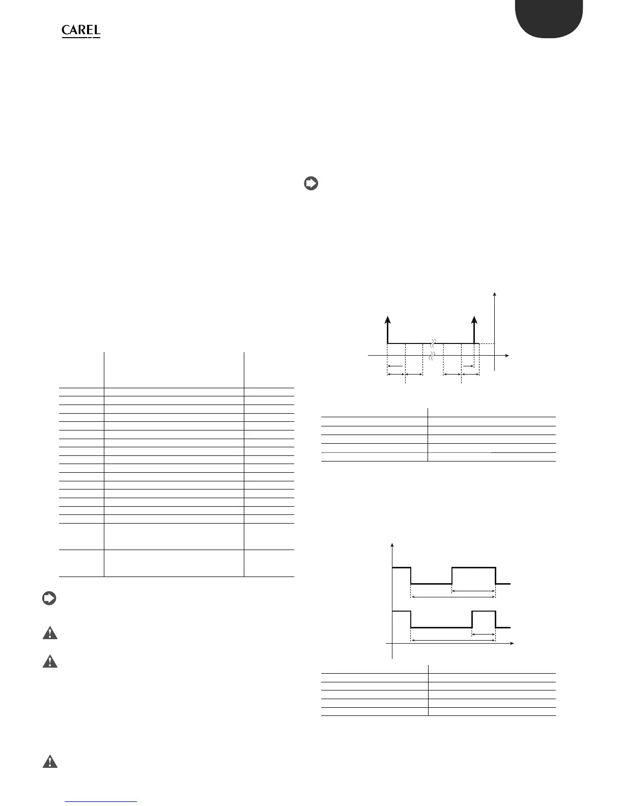
Example 1:
The gure below shows the activation points on a controller with 2
outputs, with the following parameters:
St1=10, St2=20, P1=P2=6
OUT1 (point A): “dependence”=c34=1, “activation”= c36=-100;
OUT2 (point B): “dependence”=c38=2, “activation”= c40= +75.
A=4; B=24.5
Key
St1/2 Set point 1/2
P1 Di erential for output 1
P2 Di erential for output 2
OUT1/2 Output 1/2
B1 Probe 1
Example 2
A “timer” output is selected with “dependence”=15, “type of output”=1
and “activation” (ON percentage) between 1 and 99, with a cycle time set
by c12. Below OUT1 and OUT2 are proposed as “timer” outputs with c36
greater than c40, example:
OUT1: c34=15, c35=1, c36=50; OUT2: c38=15, c39=1, c40=25.
Key
t time
c12 cycle time
OUT1/2 Output 1/2
TON_1 (c36*c12)/100
TON_2 (c40*c12)/100
5.5.4 Di erential/logic ( parameters c37,c41,c45,c49)
The “di erential/logic” parameter is only active if the output is the control
output (“dependence”=1,2,16,17). Like the “activation” parameter, it is
expressed as a percentage and is used to de ne the hysteresis of the
 Loading...


