33
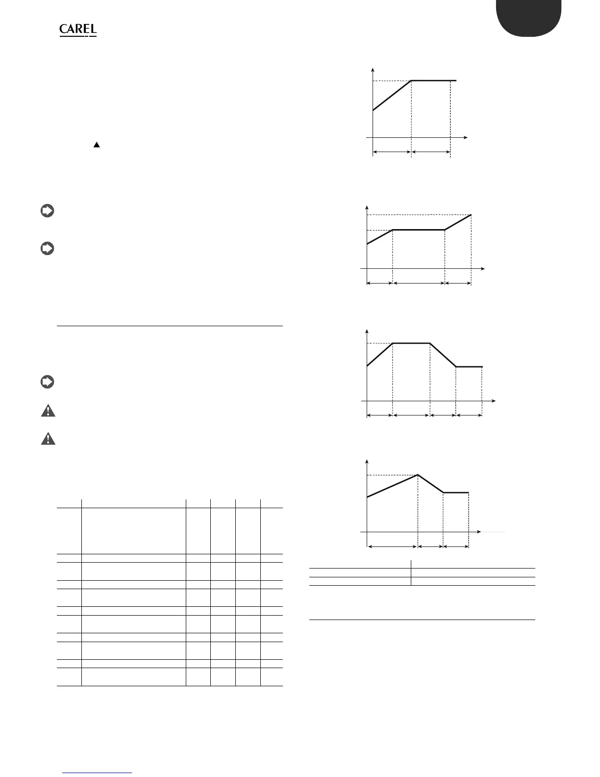
t
T
STEP1
P71=45’
P72=Set
STEP2
P73=45’
P74=Set
Set
45’45’
t
T
STEP1
P71=30’
P72=Set1
STEP2
P73=60’
P74=Set1
STEP3
P75=30’
P76=Set2
60’
Set1
Set2
30’ 30’
t
T
STEP1
P71=60’
P72=Set2
STEP2
P73=30’
P74=Set1
STEP3
P75=30’
P76=Set1
Set1
Set2
t
T
STEP1
P71=30’
P72=Set2
STEP2
P73=45’
P74=Set2
STEP3
P75=30’
P76=Set1
STEP4
P77=30’
P78=Set1
45’
Set1
Set2
60’
30’ 30’
30’ 30’
30’
ENG
ir33 universale +030220801 - rel. 1.0 - 16.04.2008
procedure can be repeated to further tune the values. This is useful when
the loads have changed since the rst procedure was performed, or to
allow ner tuning. The controller in this case can manage the system
using the PID parameters, and further Auto-Tuning will have the e ect
of improving control.
This time, the procedure can be started during normal control of the
system (with c0 =1 or 2, that is, control in “direct” or “reverse” mode, and c5
=1, that is, PID control enabled); the controller in this case does not need
to be switched o and on again; simply:
-set parameter c64 to 1;
-press the
button for 5 seconds, after which the unit will display the
message “tun” and Auto-Tuning will start.
The controller then proceeds with Auto-Tuning as already described
above. In both modes described, if the procedure ends positively, the
controller will automatically set parameter c64 to zero and will activate
PID control with the new parameters saved.
The Auto-Tuning procedure should not be considered essential in
achieving optimum control of the system; experienced users can also
achieve excellent results by setting the parameters manually.
For users experienced in operating the IR32 Universal family controllers
in P+I mode, simply set c5=1 (that is, PID control enabled) and use the
default values of the parameters, thus replicating the behaviour of the
previous model of controller.
6.4 Operating cycle
The operating cycle is an automatic program that can have a maximum
of 5 set points to be reached in the 5 respective time intervals. This may
be useful for automating processes in which the temperature must follow
a set pro le for a certain time (e.g. milk pasteurisation).
The operating cycle is started from the keypad, digital input or
automatically by RTC. See the chapter on the “User interface”.
The opening of the digital inputs does not a ect the
operating cycle, which continues as de ned by the program.
If the duration of step x, (P73, P75, P77, P79) is set a zero, it means that
the controller only manages the temperature. The controller will try to
reach the set temperature in the shortest possible time, after which it will
go to the next step. On the contrary, P71 must be set ≠ 0. With duration
of the step ≠ 0, the controller will try to reach the set temperature in the
established time, and then anyway it will go on to the next step.
Par. Description Def Min Max UoM
P70 Enable operating cycle
0=Disabled
1=Keypad
2=Digital input
3=RTC
003 -
P71 Oper. cycle: duration of step 1 0 0 200 min
P72 Operating cycle: temperature
set point step 1
0 -50 150 °C/°F
P73 Oper. cycle: duration of step 2 0 0 200 min
P74 Operating cycle: temperature
set point step 2
0 -50 150 °C/°F
P75 Oper. cycle: duration of step 3 0 0 200 min
P76 Operating cycle: temperature
set point step 3
0 -50 150 °C/°F
P77 Oper. cycle: duration of step 4 0 0 200 min
P78 Operating cycle: temperature
set point step 4
0 -50 150 °C/°F
P79 Oper. cycle: duration of step 5 0 0 200 min
P80 Operating cycle: temperature
set point step 5
0 -50 150 °C/°F
Example 1: Heating cycle with in nite temperature control
Example 2: Heating cycle with intermediate pauses and stop at the end
Example 3: Low pasteurisation cycle
Example 4: High pasteurisation cycle
Key
T Temperature
t Time
6.5 Operation with probe 2
Installing probe 2 allows various types of operation to be enabled,
selected using parameter c19
6.5.1 Di erential operation (parameter c19=1)
The second probe (B2) must be installed. Control is performed by
comparing the set point St1 against the di erence between the two
probes (B1-B2). In practice, the controller acts so that the di erence B1-B2
is equal to St1. As mentioned, the management of the second probe is
only available in modes c0=1 & 2.
“Direct” operation (c0=1) is suitable for applications in which the controller
needs to stop the di erence B1-B2 from increasing.
“Reverse” operation (c0=2), on the other hand, stops the di erence B1-B2
from decreasing. Below are some examples of applications.
 Loading...


