29
100%
0%
d40=50%
St1
B1
P1
P1/2
P1/2
100%
OUT2 OUT1
OUT2 OUT1
c0=2
c0=2
0%
d40=50%
St1
B1
P1
P1/2
P1/2
ON
OFF
St1
B1
P1
P1
b
a
ON
OFF
St1
B1
P1 P3 P3
P1
b
a
100%
OUT1
0%
St1
P1
P1
ba
100%
OUT1
0%
St1
P1 P3
P3 P1
ba
ON
OFF
St1
B1
P1
ON
OFF
St2
B1
P2
ON
OFF
St2
B1
P2
ON
OFF
St2
B1
P2
ENG
ir33 universale +030220801 - rel. 1.0 - 16.04.2008
The following must also be set:
“type of output “ =1, modulating output•
minimum modulating output value (par. d36,d40,d44,d48) > 0•
Par. Description Def Min Max UoM
c68 Enable Cut O function
0=Cut o enabled
1=Cut o disabled
001-
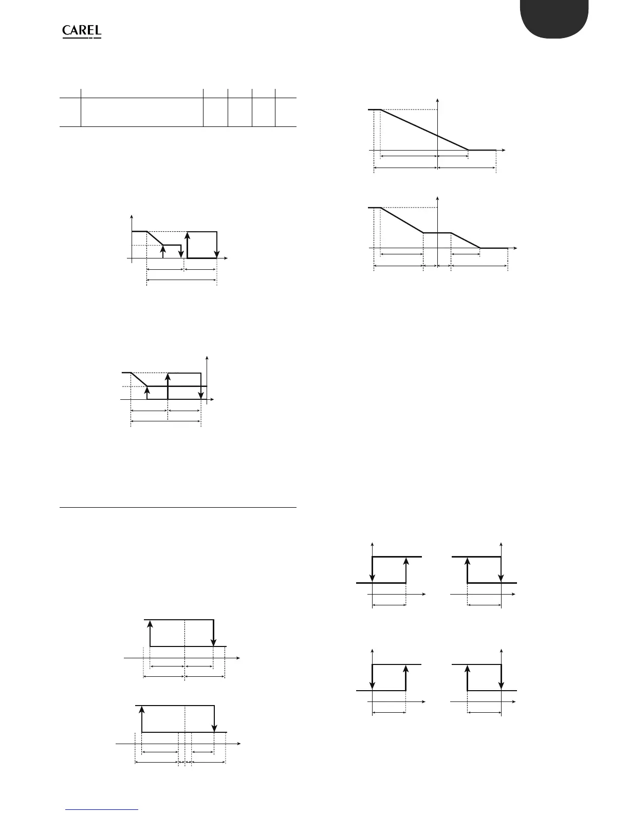
Example: control with two outputs, the rst(OUT1) ON/OFF and the
second (OUT2) 0 to 10 Vdc;
“minimum value of the modulating output” for output 2= 50 (50% of the
output), d40=50.
CASE 1: c68 = 0
CASE 2: c68 = 1
5.6 Additional remarks on special operation
Dead zone P3
In modes 3, 4 and 5 there is a dead zone de ned by P3. The activation or
deactivation points cannot be positioned inside the dead zone: if these
are identi ed in the zone before and after the set point, the instrument
automatically increases the hysteresis of the output involved by double
the value of P3.
The PWM (or analogue) outputs will follow the operation indicated in
the gure. In practice, in the dead zone the output maintains the level of
activation unchanged.
Mode 6 sees the outputs linked to St1 with “direct” logic (“activation”
positive and “di erential/logic” negative) when digital input 1 is open. The
closing of digital input 1 forces the outputs to depend on St2 and P2,
and the logic becomes “reverse”, by inverting of sign of the “activation”
and “di erential/logic” parameters (reading the values of the parameters
does not depend on the status of the digital input: these only change as
regards the algorithm). When c33=1:
“direct” and “reverse” outputs can be programmed based on “activation”
•
and “di erential/logic”. The logic de ned is valid when digital input 1 is
open, the logic is reversed when the contact closes, with the following
warnings:
if “dependence”=2 the output in question will always be linked to St2/•
P2; in practice, the “dependence” does not change when the digital
input switches.
On the other hand, the logic will always change from “direct” to “reverse”,
that is, the signs of the “activation” and “di erential/logic”. parameters are
always inverted The gure below represents an example of this. The alarm
outputs (“dependence”=3,4 to 14) do not depend on the digital input.
Dependence= 1
INPUT DI1 OPEN INPUT DI1 CLOSED
Dependence= 2
INPUT DI1 OPEN INPUT DI1 CLOSED
Modes 7 and 8. For the outputs with “dependence”=2, the changeover of
digital input 1 no longer a ects the set point, which remains St2, nor the
logic (these modes in fact do not feature changes to the logic). The alarm
outputs (“dependence”=3, 4 to 14), do not depend on digital input 1.
 Loading...


