28
c36=-100
c37=+100
c41=-50
c40=+75
OUT1
AA’ B’B
OUT2
B1
P1=6 P1=6 P2=6 P2=6
St1=10 St2=20
ON
OFF
100%
OUT1
0%
d36=20%
St1
B1
P1
100%
OUT1
0%
d37=80%
St1
B1
P1
c36=-100
OUT1
A’’ A B
B’’
OUT2
B1
P1=6 P1=6 P2=6 P2=6
St1=10 St2=20
ON
OFF
c40=+75
c41=+100
c37=-50
ENG
ir33 universale +030220801 - rel. 1.0 - 16.04.2008
output, that is, for ON/OFF operation, the deactivation point of the output
or, for PWM operation, the point where the output has the minimum value
(ON time =0). If the output refers to St1 (“dependence”=1), “di erential/
logic” is relative to the percentage value of P1; if the output refers to St2
(“dependence”= 2), “di erential/logic” is relative to the percentage value
of P2.
If the value of “di erential/logic” is positive, the deactivation point is
greater than the activation point and “reverse” logic is created.
If the value of “di erential/logic” is negative, the deactivation point is less
than the activation point and “direct” logic is created.
Together with the previous “activation” parameter, this identi es the
proportional control band.
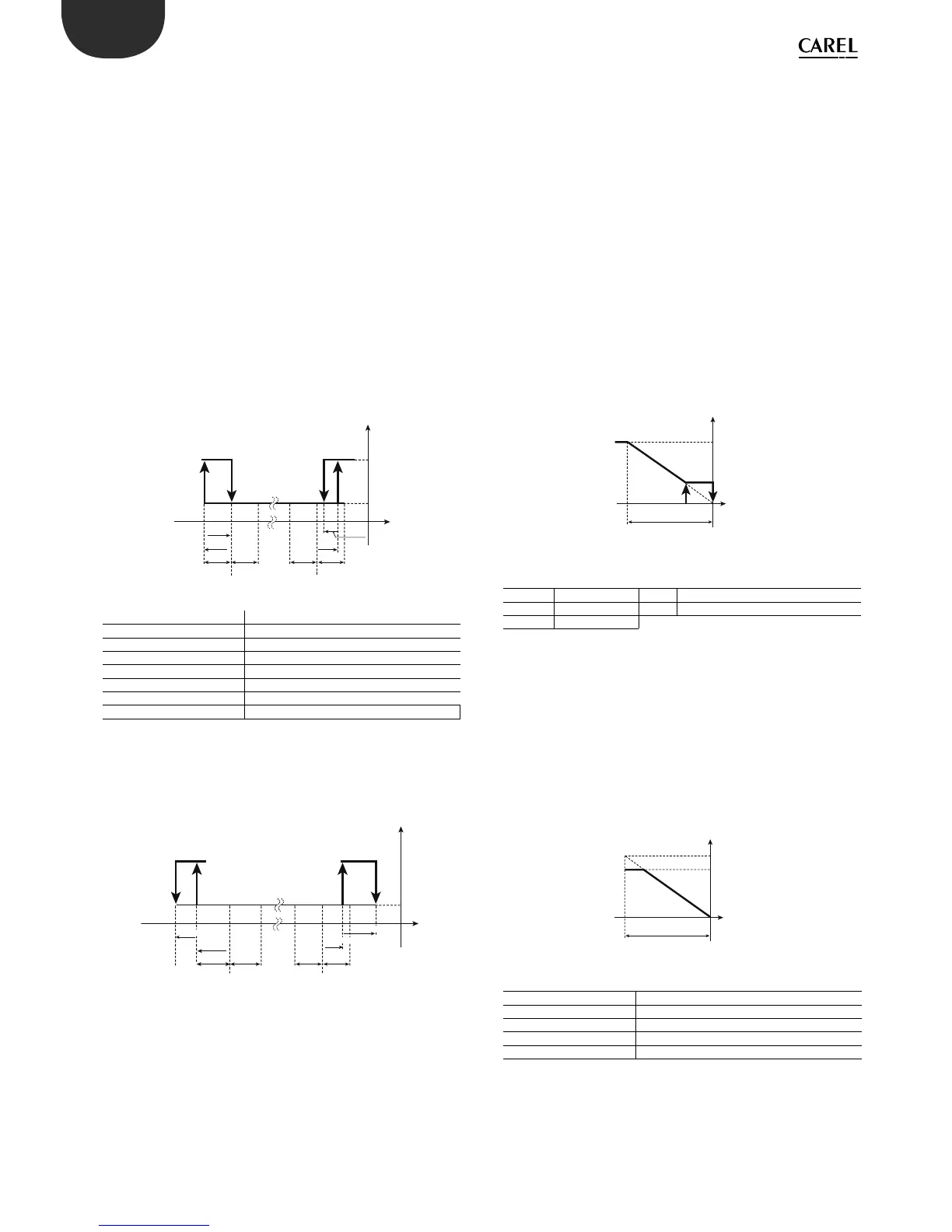
Example 3.
Example 3 completes example 1, adding the deactivation points.
For the rst output “reverse” operation is required, and the di erential P1;
for the second, “direct” logic and the di erential equal to half of P2.
The parameters are :
Output 1 : “di erential/logic”=c37=+100 (A’)
Output 2: ”di erential/logic”=c41=-50 (B’)
A’=10; B’=21.5
Key
St1/2 Set point 1/2
c36/c40 Activation of output 1/2
c37/c41 Di erential/logic for output 1/2
OUT1/2 Output 1/2
P1 Set point di erential 1
P2 Set point di erential 2
B1 Probe 1
As an example, reversing the values of “di erential/logic”, the new
deactivation points are as follows
Output 1 : “di erential/logic”=c37=-50(A’)
Output 2: ”di erential/logic”=c41=+100 (B’)
A’’=1; B’’=30.5
5.5.5 Activation restriction (par. d34,d38,d42,d46)
In normal operating conditions, the activation sequence should be as
follows: 1,2,3,4. However, due to minimum on/o times or times between
successive activations, the sequence may not be observed. By setting this
restriction, the correct sequence is observed even when timers have been
set. The output with the activation restriction set to ‘x’ (1,2,3) will only be
activated after the activation of output ‘x’. The output with the activation
restriction set to 0 will be activated irrespective of the other outputs.
5.5.6 Deactivation restriction (par. d35,d39,d43,d47)
In normal operating conditions, the deactivation sequence should be as
follows: 4,3,2,1. However, due to minimum on/o times or times between
successive activations, the sequence may not be observed. By setting
this restriction, the correct sequence is observed even when timers have
been set. The output with the deactivation restriction set to ‘x’ (1,2,3) will
only be deactivated after the deactivation of output ‘x’. The output with
the deactivation restriction set to 0 will be deactivated irrespective of the
other outputs.
5.5.7 Minimum modulating output value
(parameters d36,d40,d44,d48)
Valid if the output is the control output and the “type of output”=1, that
is, the output is PWM or in case of 0 to 10Vdc output. The modulating
output can be limited to a relative minimum value.
Example of proportional control: “reverse” mode with St1 =20°C and
P1=1°C. If only one modulating output is used with a di erential of 1°C,
setting this parameter to 20 (20%) will mean the output is only activated
when the temperature measured deviates more than 20% of the set
point, that is, with values less than 19.8°C.
Key
St1 Set point 1 P1 “Reverse” di erential
OUT1 Output 1 d36 Min. value of modulating output 1
B1 Probe 1
5.5.8 Maximum modulating output value (parameters
d37,d41,d45,d49)
Valid if the output is the control output and the “type of output”=1, that
is, the output is PWM or in case of 0 to 10Vdc output. The modulating
output can be limited to a relative maximum value.
Example of proportional control: “reverse” mode with St1 =20°C and
P1=1°C. If only one modulating output is used with a di erential of 1°C,
setting this parameter to 80 (80%) will mean the output is only activated
when the temperature measured deviates more than 80% of the set
point, that is, with values less than 19.2°C. After this value the output will
remain constant.
Key
St1 Set point 1
P1 “Reverse” di erential
d37 Maximum value of modulating output 1
OUT1 Output 1
B1 Probe 1
5.5.9 Enable modulating output Cut O (parameter
c68)
This parameter is useful when needing to apply a minimum voltage value
for the operation of an actuator.
Enable operation with a minimum limit for the output PWM and 0 to 10
Vdc analogue outputs.
 Loading...


