7
ENG
ir33 universale +030220801 - rel. 1.0 - 16.04.2008
1. INTRODUCTION
IR33-DN33 Universal is a series of controllers designed for controlling
the temperature in air-conditioning, refrigeration and heating units. The
models di er according to the type of power supply (115 to 230 Vac or
12 to 24 Vac, 12 to 30 Vdc) and the outputs, which based on the model
may be one, two or four relays, one or four PWM outputs for controlling
external solid state relays (SSR), one or two relays plus one or two 0 to
10 Vdc analogue outputs (AO) respectively. The models described in this
user manual are suitable for controlling the temperature using four types
of probes: NTC, NTC-HT (high temperature), PTC or PT1000. The type of
control can be set as ON/OFF (proportional) or proportional, integral and
derivative (PID). A second probe can be connected for di erential control
or freecooling/freeheating, or for compensation based on the outside
temperature. The range includes models for panel installation (IR33), with
IP65 index of protection, and for DIN rail mounting (DN33). To simplify
wiring, all the models are tted with plug-in terminals. The controllers
can be connected via a network to supervisory and telemaintenance
systems.
The accessories available include:
computer-based programming tool;
•
remote control for operation and programming;•
programming key, with battery;•
programming key, with 230 Vac power supply;•
RS485 serial card;•
RS485 serial card, with possibility of reversing the Rx-Tx terminals;•
module for converting the PWM signal to a 0 to 10 Vdc or 4 to 20 mA •
analogue signal;
module for converting the PWM signal to an ON/OFF relay signal.•
1.1 Models
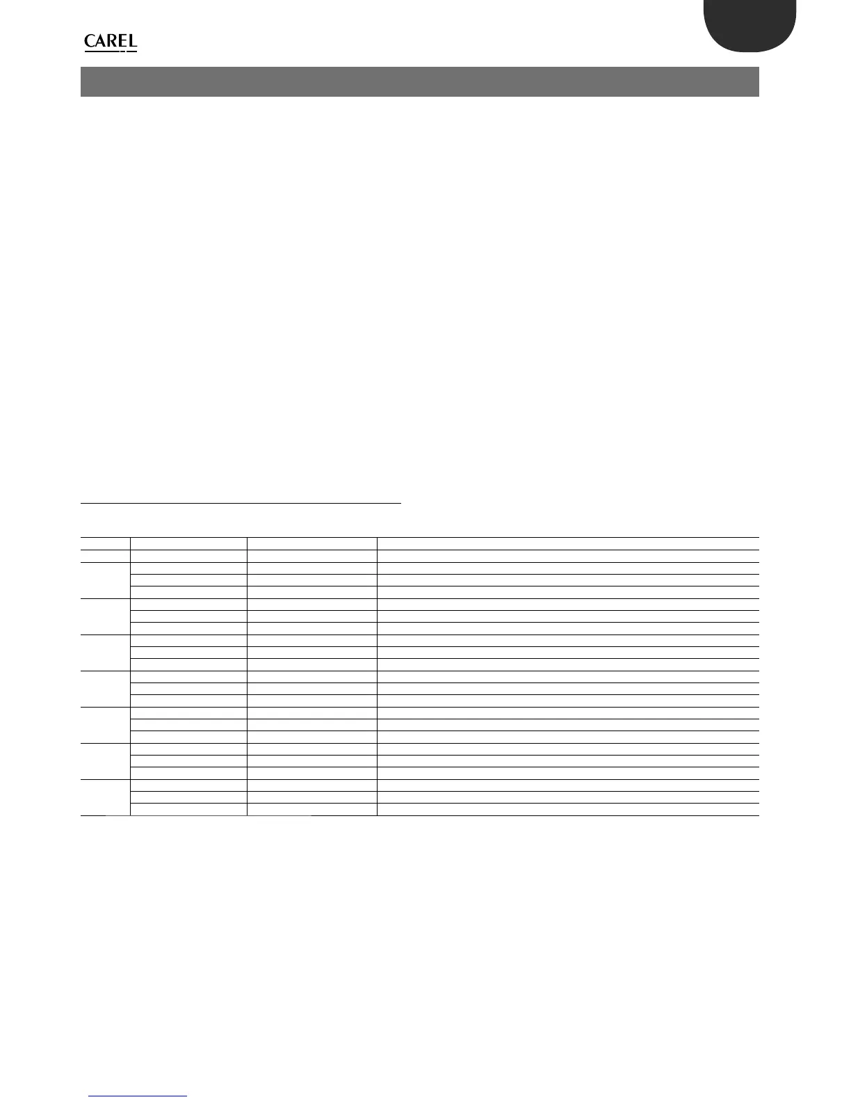
The following table describes the models and the main characteristics.
IR33-DN33 UNIVERSAL
TYPE CODE Characteristics
ush mount DIN rail mounting
1 relay
IR33V7HR20 DN33V7HR20 2 NTC/PTC/PT1000 input, 1 relay, buzzer, IR receiver, 115 to 230V
IR33V7HB20 DN33V7HB20 2 NTC/PTC/PT1000 input, 1 relay , buzzer, IR receiver, RTC, 115 to 230V
IR33V7LR20 DN33V7LR20 2 NTC/PTC/PT1000 input, 1 relay , buzzer, IR receiver, 12 to 24V
2 relays
IR33W7HR20 DN33W7HR20 2 NTC/PTC/PT1000 input, 2 relays, buzzer, IR receiver, 115 to 230V
IR33W7HB20 DN33W7HB20 2 NTC/PTC/PT1000 input, 2 relays, buzzer , IR receiver, RTC, 115 to 230V
IR33W7LR20 DN33W7LR20 2 NTC/PTC/PT1000 input, 2 relays, buzzer, IR receiver, 12 to 24V
4 relays
IR33Z7HR20 DN33Z7HR20 2 NTC/PTC/PT1000 input, 4 relays, buzzer, IR receiver, 115 to 230V
IR33Z7HB20 DN33Z7HB20 2 NTC/PTC/PT1000 input, 4 relays , buzzer, IR receiver, RTC, 115 to 230V
IR33Z7LR20 DN33Z7LR20 2 NTC/PTC/PT1000 input, 4 relays , buzzer, IR receiver, 12 to 24V
4 SSR
IR33A7HR20 DN33A7HR20 2 NTC/PTC/PT1000 input, 4 SSR, buzzer, IR receiver, 115 to 230V
IR33A7HB20 DN33A7HB20 2 NTC/PTC/PT1000 input, 4 SSR, buzzer, IR receiver, RTC, 115 to 230V
IR33A7LR20 DN33A7LR20 2 NTC/PTC/PT1000 input, 4 SSR, buzzer, IR receiver, 12 to 24V
1 SSR
IR33D7HR20 - 2 NTC/PTC/PT1000 input, 1 SSR, buzzer, IR receiver, 115 to 230V
IR33D7HB20 - 2 NTC/PTC/PT1000 input, 1 SSR, buzzer, IR receiver, RTC, 115 to 230V
IR33D7LR20 - 2 NTC/PTC/PT1000 input, 1 SSR, buzzer, IR receiver, 12 to 24V
1 relay +1
0 - 10Vdc
IR33B7HR20 DN33B7HR20 2 NTC/PTC/PT1000 input, 1 relay + 1 AO, buzzer, IR receiver, 115 to 230V
IR33B7HB20 DN33B7HB20 2 NTC/PTC/PT1000 input, 1 relay + 1 AO, buzzer, IR receiver, RTC, 115 to 230V
IR33B7LR20 DN33B7LR20 2 NTC/PTC/PT1000 input, 1 relay + 1 AO, buzzer, IR receiver, 12 to 24V
2 rel. +2 x
0 -10Vdc
IR33E7HR20 DN33E7HR20 2 NTC/PTC/PT1000 input, 2 relays + 2 AO, buzzer, IR receiver, 115 to 230V
IR33E7HB20 DN33E7HB20 2 NTC/PTC/PT1000 input, 2 relays + 2 AO, buzzer, IR receiver, RTC, 115 to 230V
IR33E7LR20 DN33E7LR20 2 NTC/PTC/PT1000 input, 2 relays + 2 AO, buzzer, IR receiver, 12 to 24V
Tab. 1. a
RTC = Real Time Clock
Note that the type of outputs can be identi ed from the code:
the fth letter V/W/Z corresponds to 1,2,4 relay outputs respectively;•
the fth letter D/A corresponds to 1 or 4 PWM outputs respectively; •
the fth letter B/E corresponds to 1 or 2 relays and 1 or 2 x 0 to 10 Vdc •
analogue outputs respectively.
The type of power supply can also be identi ed:
the seventh letter H corresponds to the 115 to 230 Vac power supply;•
the seventh letter L indicates the 12 to 24 Vac or 12 to 30Vdc power •
supply.
 Loading...


