34
B1 (T1) B2 (T2)
CHILLER
St1=5
OUT2 OUT1
Mod. W
B1-B2
P1
ON
OFF
B2 (T1) B1 (T2)
CHILLER
St1=-5
OUT1 OUT2
Mod. W
B1-B2
P1
ON
OFF
L Ncompressor 1
OUT2 OUT3
OUT4
OUT1
compressor 2
alarm
P25=6 St2=8
OUT1 (LOW ALARM) OUT2
Mod. Z
B1 (T2)
P2P27
ON
OFF
St1=-5
OUT3 OUT4
Mod. W
B1-B2
P1
ON
OFF
ENG
ir33 universale +030220801 - rel. 1.0 - 16.04.2008
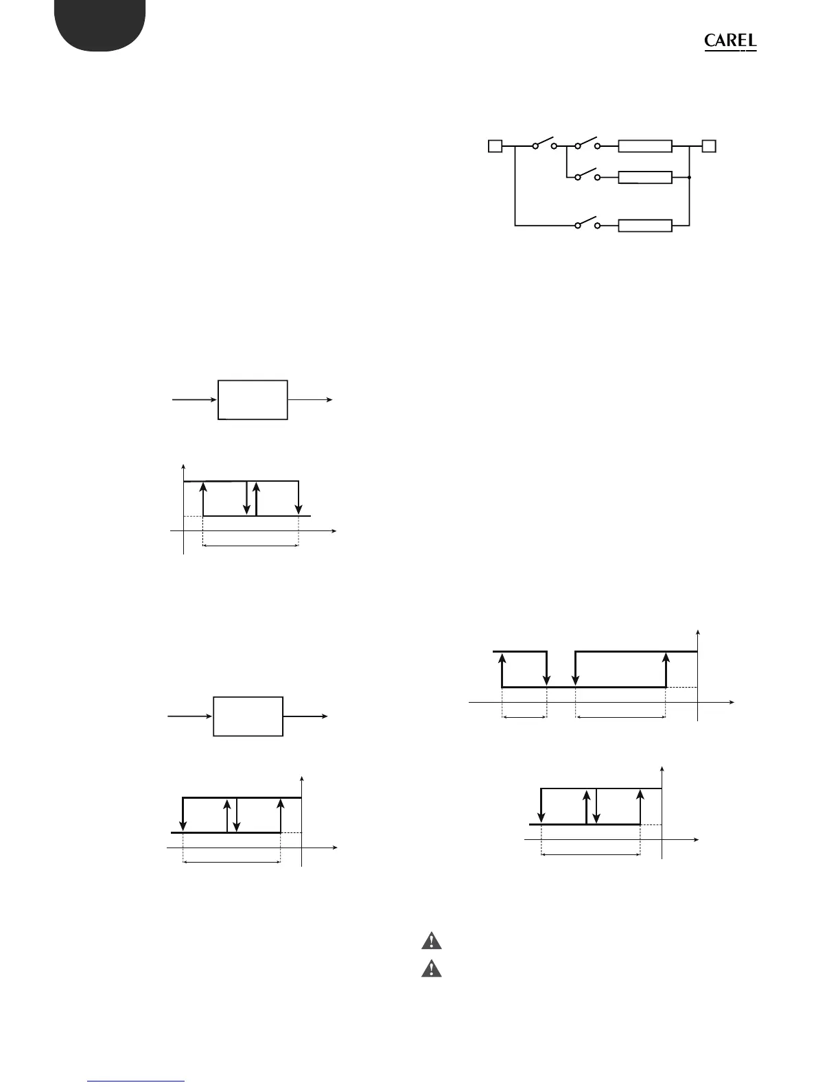
Example 1:
A refrigeration unit with 2 compressors must lower the temperature of
the water by 5°C.
Introduction: having selected a controller with 2 outputs to manage the
2 compressors, the rst problem to be faced relates to the positioning
of probes B1 and B2. Remember that any temperature alarms can only
refer to the value read by probe B1. The example indicates the inlet
temperature as T1 and the outlet temperature as T2.
Solution 1a: install B1 on the water inlet if it is more important to control
the inlet temperature T1; that will allow alarm signals, where necessary
delayed, relating to a “High” inlet temperature T1. For example, when
B1=T1 the set point corresponds to “B1-B2”, i.e. “T1-T2”, and must be equal
to +5°C (St1=5). The operating mode will be “reverse” (c0=2), given that
the controller activates the outputs as the value of “T1-T2” decreases,
and tends towards 0. Choosing a di erential equal to 2°C (P1=2), a high
temperature threshold equal to 40°C (P26=40) and a delay of 30 minutes
(P28=30), the operation will be as described in the following gure.
Solution 1b: if on the other hand priority is attributed to T2 (e.g. “Low
temperature” threshold 6°C with a one minute delay), the main probe,
B1, must be set as the outlet temperature. With these new conditions,
the set point St1, equal to “B1-B2”, i.e. ‘T2-T1’, must now be set to -5°C.
The operating mode will be “direct” (c0=1), given that the controller must
activate the outputs as the value of ‘T2-T1’ increases, and from -5 tends
towards 0. P25=6 and P28=1(min) activate the “Low temperature” alarm,
as shown in the new control logic diagram:
Example 1 (continued)
Example 1 can be resolved using “special” operation (c33=1). Starting
from solution 1b (T2 must be 5°C less than T1). The main probe is located
at the outlet (T2 =B1).
These requirements also need to be satis ed:
• the outlet temperature T2 must remain above 8°C;
• if T2 remains below 6°C for more than one minute, a “Low temperature”
alarm must be signalled.
Solution: use a controller with 4 outputs (IR33Z****); two outputs are
used for control (OUT3 and OUT4), and one for the remote alarm signal
(OUT1). OUT2 will be used to deactivate outputs OUT3 and OUT4 when
T2< 8°C. To do this, simply connect OUT2 in series with OUT3 and OUT4,
then make OUT2 active only when B1 (T2) is greater than 8°C.
Set c33=1: the changes to be made to the special parameters are:
Output 1: must be programmed as an alarm output that is active only
for the “Low temperature” alarm. Set “dependence”=c34, which changes
from 1 to 9 (or 10 to use normally ON relays). The other parameters for
output 1 are not relevant and remain unchanged.
Output 2: this becomes detached from di erential operation, changing
the “dependence” from 1 to 2: “dependence”=c38=2. The logic is “direct”
and includes all of P2, therefore “activation” =c40 becomes 100, and
“di erential/logic”=c41 becomes -100. St2 will obviously be set to 8 and
P2 represents the minimum variation required to restart control, once it
has stopped due to “Low temperature”, e.g. P2=4.
Output 3 and Output 4: in the controllers with 4 outputs, mode 1 assigns
each output an hysteresis of 25% of the di erential P1. In the example,
considering that 2 outputs are used for control, the hysteresis for
each output must be 50% of P1. The “activation” and “di erential/logic”
parameters for the outputs must be changed to suit the new situation.
In practice, this means setting:
Output 3:
“activation”=c44 changes from 75 to 50
“di erential/logic”=c45, changes from -25 to -50.
Output 4:
“activation”=c48 remains at 100
“di erential/logic” = c49 changes from -25 to -50.
The diagram summarises the controller operating logic.
6.5.2 Compensation
The compensation function is used to modify the control set point St1
according to the reading of the second probe B2 and the reference set point
St2. Compensation has a weight equal to c4, called the “authority”.
The compensation function can only be activated when c0=1,2.
When compensation is in progress, parameter St1 remains at the set
value; on the other hand, the operating value of St1 changes, known
as the e ective St1, that is, the value used by the control algorithm. The
e ective St1 is also restricted by the limits c21 and c22 (minimum and
maximum value of St1); these two parameters guarantee that St1 does
not reach undesired values.
 Loading...


