35
St2
c4= 2
c4=+0,5
c4=-0,5
B2
c22
St1_comp
c21
St1
c4= -2
St2
c4=-2
c4=+0,5
c4=-0,5
B2
c22
St1_comp
c21
St1
c4=2
St1_comp
c22=27
24
St2=24 34 B2
c4=0,3
St1_comp
13
c21=10
St2=28 34 B2
c4=-0,5
St1_comp
c22=85
70
St2=15
0
B2
c4=-1
ENG
ir33 universale +030220801 - rel. 1.0 - 16.04.2008
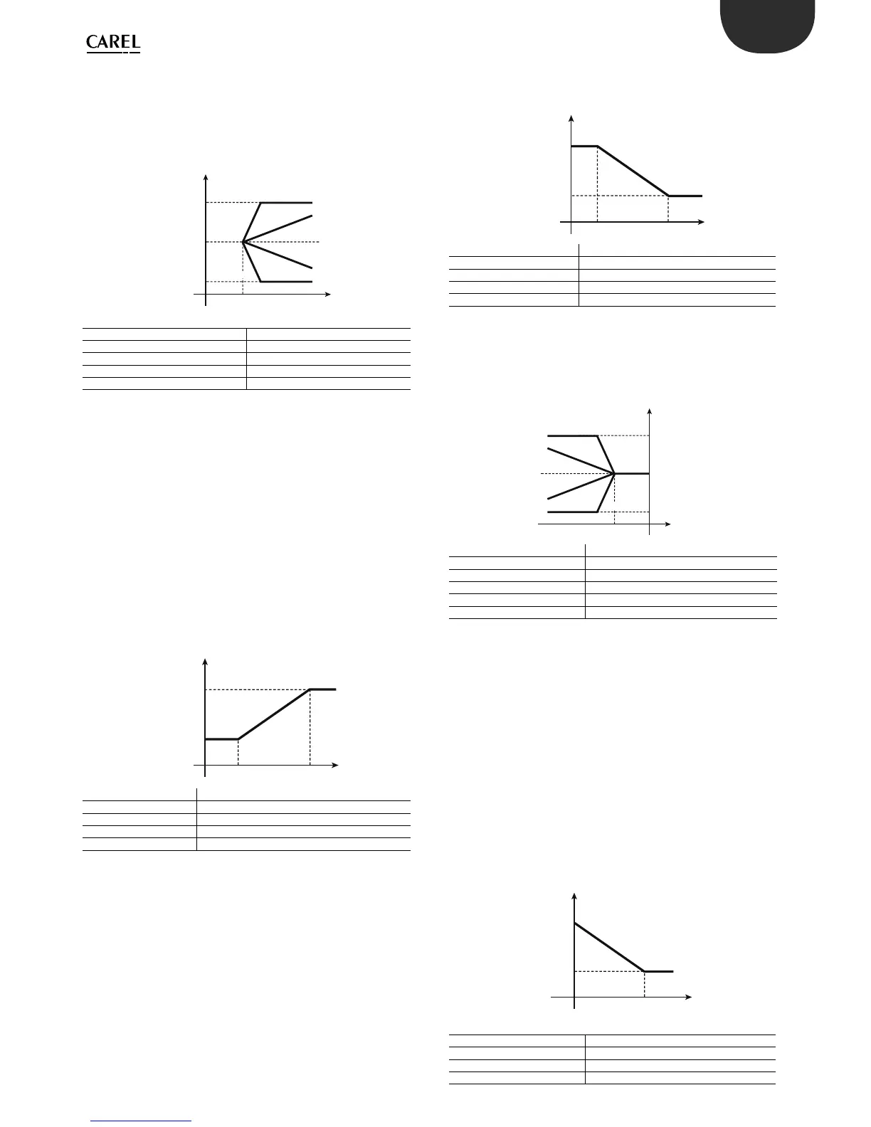
6.5.3 Compensation in cooling (parameter c19=2)
Compensation in cooling may either increase or decrease the value of
St1, depending on whether c4 is positive or negative.
St1 only changes if the temperature B2 exceeds St2:
• if B2 is greater than St2 then: e ective St1 = St1 + (B2-St2)*c4
• if B2 is less than St2: e ective St1 = St1
Key:
St1_comp E ective set point 1
B2 Outside probe
c4 Authority
c21 Minimum value of set point 1
c22 Maximum value of set point 1
Example 1:
The bar in a service station needs to be air-conditioned so that the
temperature is summer is around 24°C. To prevent the customers, who
only stay for a few minutes, from experiencing considerable di erences in
temperature, the inside temperature is linked to the outside temperature,
that is, it increases proportionally up to a maximum value of 27°C, when
the outside temperature is 34°C or higher.
Solution: a controller is used to manage a direct expansion air/air unit.
The main probe B1 is installed in the bar, the controller works in mode
c0=1 (direct) with set point=24°C (St1=24) and di erential e.g. 1°C (P1=1).
To exploit compensation in cooling mode, install probe B2 outside and
set c19=2. Then set St2=24, given that the requirement is to compensate
set point 1 only when the outside temperature exceeds 24 °C. The
authority c4 must be 0.3, so that with variations in B2 from 24 to 34°C,
St1 changes from 24 to 27°C. Finally, select c22=27 to set the maximum
value for the e ective St1. The graph shows how St1 changes according
to the temperature B2.
Key:
St1_comp E ective set point 1
B2 Outside probe
c4 Authority
c22 Maximum value of set point 1
Example 2:
This example involves compensation in cooling with a negative c4. The
air-conditioning system consists of a water chiller and some fan coil units.
When the outside temperature is below 28°C, the chiller inlet temperature
can be xed at St1=13°C. If the outside temperature increases, to
compensate for the greater thermal load, the inlet temperature can be
lowered down to a minimum limit of 10°C, reached when the temperature
is greater than or equal to 34°C.
Solution: the parameters to be set on the controller, with one or more
outputs in relation to the characteristics of the chiller, will be as follows:
c0=1, main probe B1 on the chiller inlet, with a main control set point
•
St1=13°C and di erential P1=2.0°C.
For compensation in cooling: c19=2, enabled for outside temperatures,
measured by B2, greater than 28°C, therefore St2=28. The authority,
considering that St1 must be lowered by 3°C in response to a variation in
B2 of 6°C (34-28), will be c4= -0.5. Finally, to prevent the inlet temperature
from falling below 10°C, a minimum limit must be set for St1, with c21=10.
The graph below shows the trend in St1.
Key:
St1_comp E ective set point 1
B2 Outside probe
c4 Authority
c21 Minimum value of set point 1
6.5.4 Compensation in heating (parameter c19=3)
Compensation in heating can increase or decrease the value of St1
depending on whether c4 is negative or positive respectively.
St1 only varied if the temperature B2 is less than St2:
if B2 is lower than St2 then: e ective St1 = St1 + (B2-St2)*c4•
if B2 is greater than St2: e ective St1 = St1•
Key:
St1_comp E ective set point 1
B2 Outside probe
c4 Authority
c21 Minimum value of set point 1
c22 Maximum value of set point 1
Example 4:
The design speci cations are as follows: in order to optimise the e ciency
of a boiler in a home heating system, the operating temperature (St1) can
be set at 70°C for outside temperatures above 15°C. When the outside
temperature drops, the operating temperature of the boiler must increase
proportionally, until reaching ad a maximum temperature of 85°C when
the outside temperature is less than or equal to 0°C.
Solution: use a controller with the main probe B1 on the water circuit,
mode 2 (heating), set point St1=70 and di erential P1=4. In addition,
probe B2 must be installed outside and compensation enabled in
heating (c19=3) with St2=15, so that the function is only activated when
the outside temperature is less than 15°C. To calculate the authority”,
consider that in response to a variation in B2 of -15°C (from +15 to 0°C),
St1 must change by +15°C (from 70°C to 85°C), so c4= -1.
Finally, set the maximum limit for St1, selecting c22=85°C. The following
graph shows how St1 varies as the outside temperature measured by B2
decreases.
Key:
St1_comp E ective set point 1
B2 Outside probe
c4 Authority
c22 Maximum value of set point 1
 Loading...


