36
St1_comp
c4>0
c22
c21
B2
P2P2
St1_comp
c4<0
c22
c21
B2
P2P2
St1
OUT2 OUT1
OUT
B1
P1
100%
0%
St1
C19=5
OUT2OUT1
OUT
B1
P1
100%
0%
c67-1,5 c67
ABILITAZIONE/
ENABLE
B2
ON
OFF
C19=6
c67-1,5
c67
ABILITAZIONE/
ENABLE
B2-B1
ON
OFF
C19=5
c66 c66+1,5
ABILITAZIONE/
ENABLE
B2
ON
OFF
C19=6
c66 c66+1,5
ABILITAZIONE/
ENABLE
B2-B1
ON
OFF
ENG
ir33 universale +030220801 - rel. 1.0 - 16.04.2008
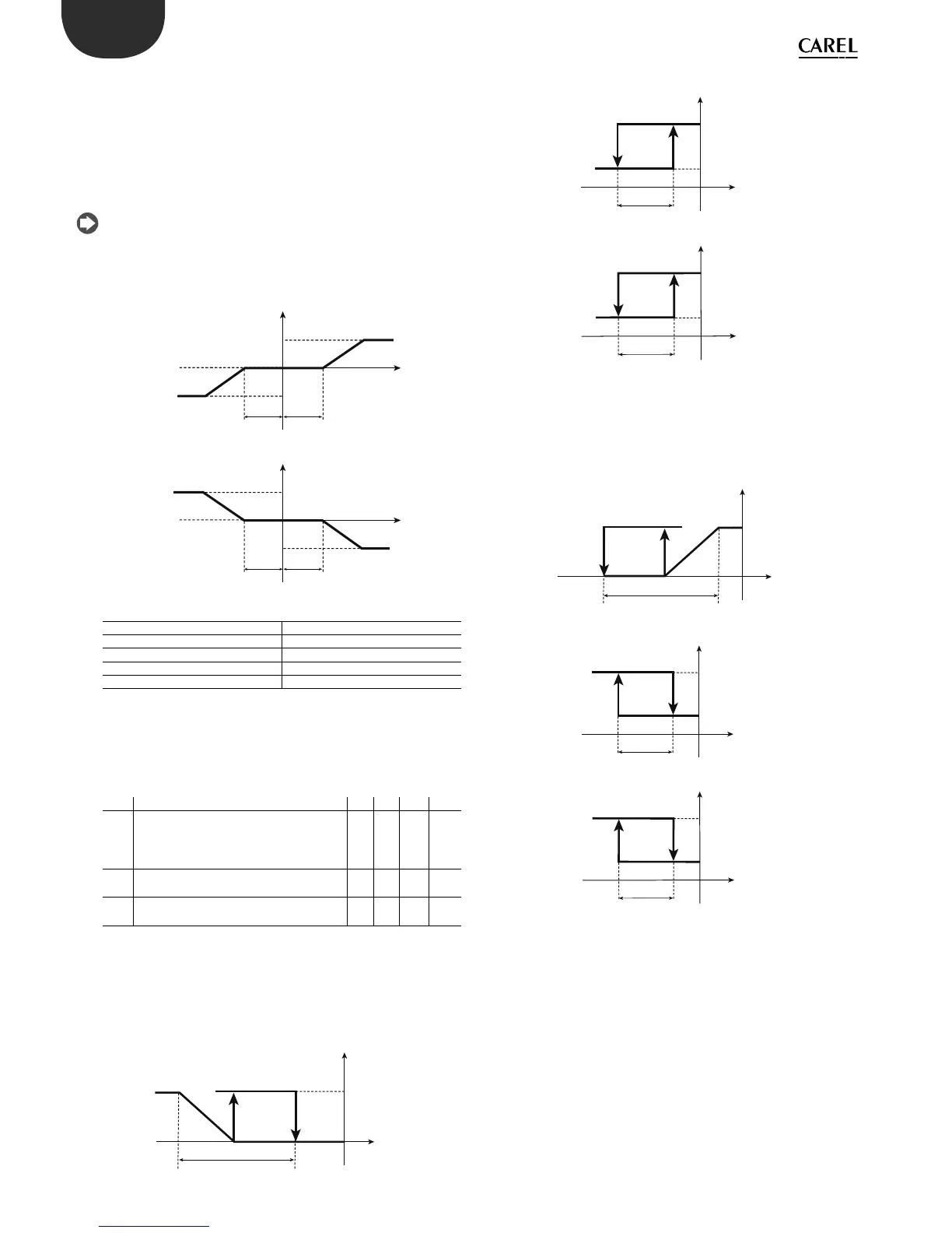
6.5.5 Continuous compensation (parameter c19=4)
The compensation of St1 is active for values of B2 other than St2: with
this value of c19, parameter P2 can be used to de ne a dead zone around
St2 in which compensation is not active, that is, when the value read by
B2 is between St2-P2 and St2+P2, compensation is disabled and St1 is
not changed:
if B2 is greater than (St2+P2), e ective St1 = St1+ [B2-(St2+P2)]*c4
if B2 is between (St2-P2) and (St2+P2), e ective St1 =St1
if B2 is less than (St2-P2), e ective St1 = St1+ [B2-(St2-P2)]*c4
Compensation using c19=4 is the combined action of compensation in
cooling and compensation in heating, as described above. The following
diagrams show continuous compensation for positive and negative
values of c4. Neglecting the e ect of P2, if c4 is positive St1 increases
when B2>St2 and decreases when B2<St2. Vice-versa, if c4 is negative St1
decreases when B2 > St2 and increases when B2 is below St2.
Key:
St1_comp E ective set point 1
B2 Outside probe
c4 Authority
c22 Maximum value of set point 1
c21 Minimum value of set point 1
6.5.6 Enable logic on absolute set point & di erential
set point (parameter c19=5,6)
When c19=5 the value read by probe B2 is used to enable control logic in
both direct and reverse mode.
If c19=6 the value considered is B2-B1.
Par. Description Def Min Max UoM
c19 Operation of probe 2
5=enable logic on absolute set point
6=enable logic on di erential set point
Validity: c0=1 or 2
006 -
c66 Enabling direct threshold
Validity: c0=1 or 2
-50 -50 150 °C/°F
c67 Enabling reverse threshold
Validity: c0=1 or 2
150 -50 150 °C/°F
“Reverse” control with enabling of “direct” logic:
Looking at the example of a controller with two outputs, one of which
ON/OFF and the other 0 to 10 Vdc. When the temperature read by probe
B2, if c19=5, or the di erence B2-B1, if c19=6, exceeds the threshold c66
(plus an hysteresis of 1.5°C to avoid swings), control is enabled on St1 and
P1; below this temperature, control is disabled.
“Direct” control with enabling of “reverse” logic:
In this case too, a controller with two outputs, one of which a ON/OFF
and the other 0 to 10 Vdc. When the temperature read by probe B2, if
c19=5 or the di erence B2-B1, if c19=6, falls below the threshold c67
(beyond an hysteresis of 1.5°C to avoid swings), control is enabled on St1
and P1; above this temperature, control is disabled.
6.5.7 Using the CONV0/10A0 module (accessory)
This module converts a 0 to 12 Vdc PWM signal for solid state relays to a linear
0 to 10 Vdc and 4 to 20 mA analogue signal.
Programming: to get the modulating output signal, the PWM control mode is
used (see the explanation for parameter c12). The PWM signal is reproduced
exactly as an analogue signal: the percentage ON time corresponds to the
percentage of the maximum output signal. The optional CONV0/10A0 module
integrates the signal provided by the controller: the cycle time (c12) must be
reduced to the minimum value available, that is, c12=0.2 s. As concerns the
control logic (“direct”=cooling, “reverse”=heating), the same observations
seen for PWM operation apply (see mode 4): the PWM activation logic is
faithfully reproduced as an analogue signal. If, on the other hand, a custom
con guration is required, refer to the paragraphs on special operation (“type
of output”, ”activation”, “di erential/logic” parameters).
 Loading...


