25
ON
OUT1 (LOW ALARM)
Mod. V
Mod. Z
OFF
B1P27
P25
ON
OFF
B1P27
P26
P27
P25
St1
St1
P26
ON
OUT1
Mod. W
OUT2 (HIGH ALARM)
OUT3 (LOW ALARM) OUT4 (HIGH ALARM)
OFF
B1P1 P3
OUT1
B1P1 P3 P3
P27
OUT2
P2
ON
OUT1
Mod. V
OFF
St1
B1
P1
ON
OUT1
Mod. V
OFF
St2
B1
P2
ON
OUT1
Mod. V
OFF
St1
B1
P1
ON
OUT1
Mod. V
OFF
St2
B1
P2
ON
OUT1
Mod. V
OFF
St1
B1
P1
ON
OUT1
Mod. V
OFF
St2
B1
P2
ENG
ir33 universale +030220801 - rel. 1.0 - 16.04.2008
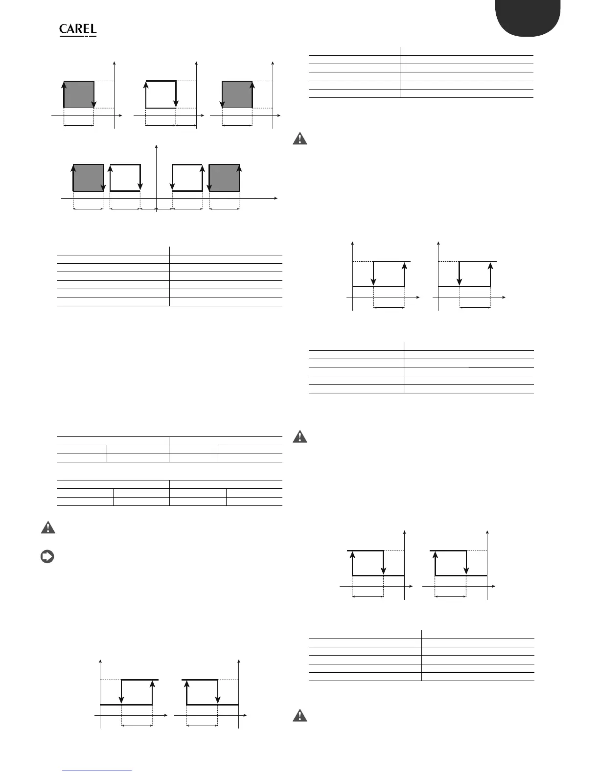
Key
St1 Set point 1
P1 “Reverse” di erential
P2 “Direct” di erential
P3 Dead zone di erential
P27 Alarm di erential
OUT1/2/3/4 Output 1/2/3/4
B1 Probe 1
Parameter P28 represents the “alarm activation delay” in minutes; the
low temperature alarm (E05) is activated only if the temperature remains
below the value of P25 for a time greater than P28. The alarm may relative
or absolute, depending on the value of parameter P29. In the former case
(P29=0), the value of P25 indicates the deviation from the set point and
thus the activation point for the low temperature alarm is: set point - P25.
If the set point changes, the activation point also changes automatically.
In the latter case (P29=1), the value of P25 indicates the low temperature
alarm threshold. The low temperature alarm active is signalled by
the buzzer and code E05 on the display. The same applies to the high
temperature alarm (E04), with P26 instead of P25.
Alarm set point relative to working set point P29=0
Low temperature alarm High temperature alarm
Enable Disable Enable Disable
Setpoint-P25 Setpoint-P25+P27 Setpoint+P26 Setpoint +P26-P27
Absolute alarm set point P29=1
Low temperature alarm High temperature alarm
Enable Disable Enable Disable
P25 P25+P27 P26 P26-P27
The low and high temperature alarms are automatically reset; if there is
an alarm active on the control probe, these alarms are deactivated and
monitoring is reinitialised.
When alarms E04 and E05 are active, the buzzer can be muted by pressing
Prg/mute. The display remains active.
5.2.6 Direct/reverse with changeover from digital input
1 (parameter c0=6)
The controller operates in “direct” mode based on St1 when digital input
1 is open, in “reverse” based on St2 when it is closed.
INPUT DI1 OPEN INPUT DI1 CLOSED
Key
St1/St2 Set point 1/2
P1 “Direct” di erential
P2 “Reverse” di erential
OUT1 Output 1
B1 Probe 1
For models W & Z the activations of the outputs are equally distributed
inside the di erential set (P1/P2).
Parameter c29 is not active in mode 6.
5.2.7 Direct with set point & di erential, changeover
from digital input 1 (parameter c0=7)
The controller always operates in “reverse” mode, based on St1 when
digital input 1 is open and based on St2 when it is closed.
INPUT DI1 OPEN INPUT DI1 CLOSED
Key
St1/St2 Set point 1/2
P1 “Direct” di erential St1
P2 “Direct” di erential St2
OUT1 Output 1
B1 Probe 1
For models W & Z the activations of the outputs are equally distributed
across the di erential (P1/P2).
Parameter c29 is not active in mode 7.
5.2.8 Reverse with set point & di erential, changeover
from digital input 1 (parameter c0=8)
The controller always operates in “reverse” mode, based on St1 when
digital input 1 is open and based on St2 when it is closed.
INPUT DI1 OPEN INPUT DI1 CLOSED
Key
St1/St2 Set point 1/2
OUT1 Output 1
P1 “Reverse” di erential
B1 Probe 1
P2 “Reverse” di erential
For models W & Z the activations of the outputs are equally distributed
across the di erential (P1/P2).
Parameter c29 is not active in mode 8.
 Loading...


