24
ON
OUT1
Mod. V
OFF
ON
OFF
St1
B1P1
OUT1OUT2
Mod. W
St1
B1
P1
ON
OUT1OUT2OUT3OUT4
Mod. Z
OFF
St1
B1
P1
ON
OUT1
Mod. V
OFF
St1
B1P1 P3
OUT1 OUT2
Mod. W
St1
B1P1 P3 P3
P2
OUT1OUT2 OUT4OUT3
Mod. Z
St1
B1
P1 P3 P3 P2
100%
OUT1
Mod. V
0%
St1
B1P1 P3
100%
OUT1
Mod. W
0%
St1
B1P1 P3
OUT2
P2P3
100%
OUT1OUT2
Mod. Z
0%
St1
B1P1/2
P1/2 P2/2P3
OUT3 OUT4
P2/2P3
ENG
ir33 universale +030220801 - rel. 1.0 - 16.04.2008
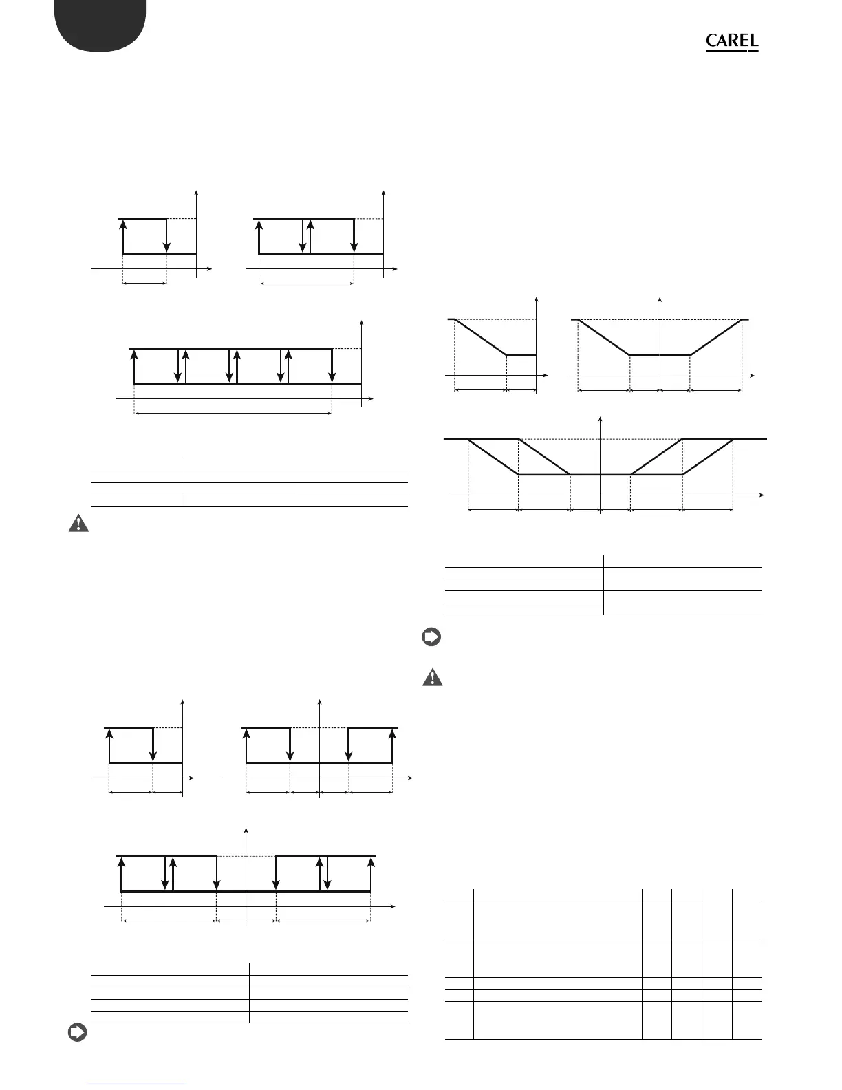
5.2.2 Reverse (parameter c0=2)
“Reverse” operation is similar to ”direct” operation, however the outputs
are activated when the value being controlled decreases, starting from
the set point (St1). When the value measured is less than or equal to
St1-P1 (in proportional only operation), all the outputs are activated.
Similarly, if the value measured starts rising, the outputs are deactivated
in sequence. When reaching St1, all the outputs are deactivated.
Key
St1 Set point 1
P1 Set point di erential 1
OUT1/2/3/4 Output 1/2/3/4
B1 Probe 1
This is the default setting.
5.2.3 Dead zone (parameter c0=3)
The aim of this control mode is to bring the measured value within an
interval around the set point (St1), called the dead zone. The extent of the
dead zone depends on the value of parameter P3. Inside the dead zone, the
controller does not activate any outputs, while outside it works in “direct”
mode when the temperature is increasing and in “reverse” mode when it
is decreasing. According to the model used, there may be one or more
outputs in “direct” and “reverse” modes. These are activated or deactivated
one at a time, as already described for modes 1 & 2, according to the value
measured and the settings of St1, P1 and P2.
Key
St1 Set point 1
P1/P2 “Reverse”/”direct” di erential
P3 Dead zone di erential
OUT1/2/3/4 Output 1/2/3/4
B1 Probe 1
When the controller only has 1 output, it works in “reverse” mode with
dead zone.
5.2.4 PWM (parameter c0=4)
The control logic in PWM mode uses the dead zone, with the outputs
activated based on pulse width modulation (PWM). The output is
activated in a period equal to the value of parameter c12 for a variable
time, calculated as a percentage; the ON time is proportional to the value
measured by B1 inside the di erential. For small deviations, the output will
be activated for a short time. When exceeding the di erential, the output
will be always on (100% ON). PWM operation thus allows “proportional”
control of actuators with typically ON/OFF operation (e.g. electric heaters),
so as to improve temperature control. PWM operation can also be used to
gave a modulating 0 to 10 Vdc or 4 to 20 mA control signal on IR33 (DN33)
Universal models A, D with outputs for controlling solid state relays (SSR).
In this case, the accessory code CONV0/10A0 needs to be connected to
convert the signal. In PWM operation, the “direct”/”reverse” icon ashes.
Key
St1 Set point 1
P1/P2 “Reverse”/”direct” di erential
P3 Dead zone di erential
OUT1/2/3/4 Output 1/2/3/4
B1 Probe 1
When the controller only has 1 output, it works in “reverse” mode with
dead zone.
PWM mode should not be used with compressors or other actuators
whose reliability may be a ected by starting/stopping too frequently.
For relay outputs, parameter c12 should not be set too low, so as to not
compromise the life of the component..
5.2.5 Alarm (parameter c0=5)
In mode 5, one or more outputs are activated to signal a probe
disconnected or short-circuited alarm or a high or low temperature alarm.
Models V and W only have one alarm relay, while model Z has two: relay
3 is activated for general alarms and for the low temperature alarm, relays
4 is activated for general alarms and for the high temperature alarm. The
activation of the alarm relay is cumulative to the other signals in the other
operating modes, that is, alarm code on the display and audible signal.
For models W & Z, the relays not used to signal the alarms are used for
control, as for mode 3 and shown the following diagrams. This operation
mode is not suitable for the models B and E.
Par. Description Def Min Max UoM
P25 Low temperature alarm threshold
P29=0, P25=0: threshold disabled;
P29=1, P25= -50: thresh. disabled
-50 -50 P26 °C/°F
P26 High temperature alarm threshold
P29=0, P26=0: threshold disabled;
P29=1, P26= 150: thresh. disabled
150 P25 150 °C/°F
P27 Alarm di erential 2 0 50 °C/°F
P28 Alarm delay time 120 0 250 min
P29 Type of alarm threshold
0=relative;
1=absolute.
101-
 Loading...


