38
ENG
ir33plus +0300028EN rel. 1.1 - 05.05.2017
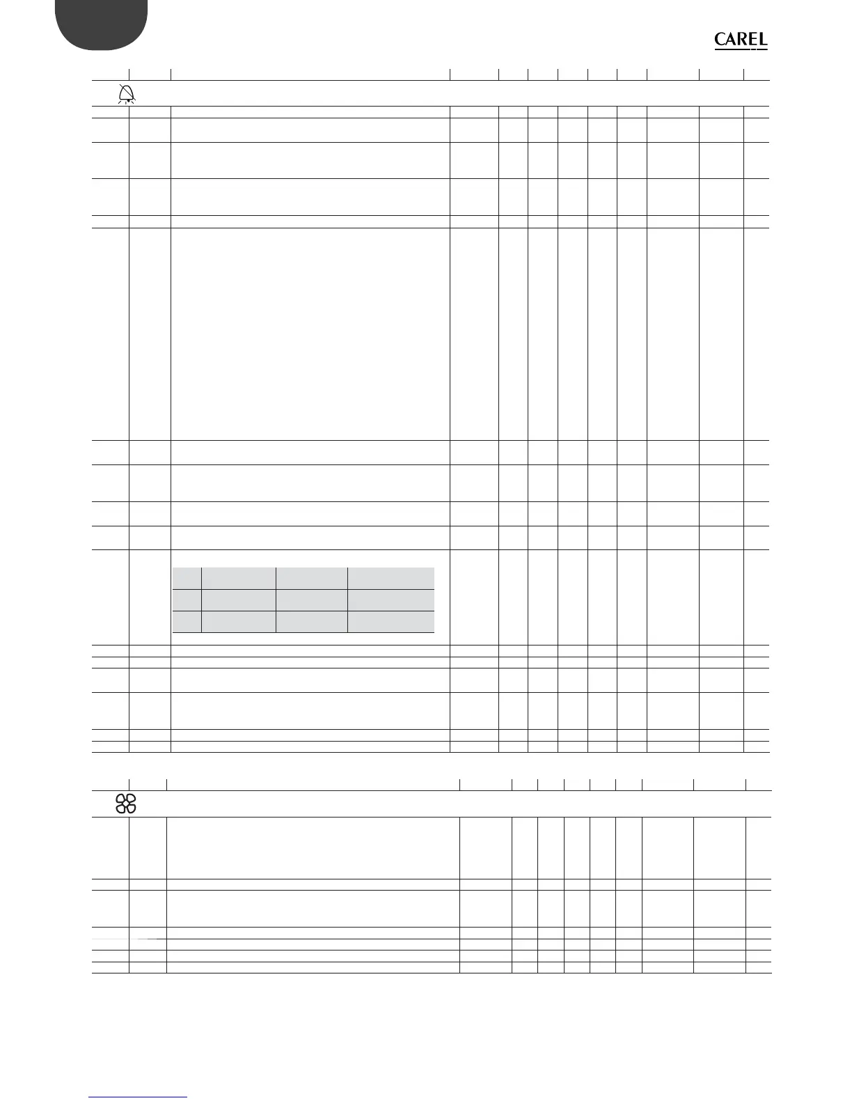
User Par. Description Models Def Min Max UOM Type CAREL SVP ModBus® R/W
ALM
C A0 Alarm and fan di erential MSYFCH 2.0 0.1 20 °C/°F A 26 26 R/W
C A1 Alarm thresholds (AL, AH) relative to set point or absolute
0/1=relative/absolute
MSYFCH 001- D48 48 R/W
F AL Low temperature alarm threshold
If A1= 0, AL=0: alarm disabled
If A1= 1, AL=-50: alarm disabled
MSYFCH 0.0 -50 200 °C/°F A 27 27 R/W
F AH High temperature alarm threshold
If A1= 0, AL=0: alarm disabled
If A1= 1, AL=200: alarm disabled
MSYFCH 0.0 -50 200 °C/°F A 28 28 R/W
F Ad High and low temperature alarm delay MSYFCH 120 0 250 min I 50 150 R/W
C A4 Digital input con guration 1 (DI1)
0 = not active
1 = immediate external alarm
2 = delayed external alarm
3 = select probes (ir33M) / enable defrost
4 = start defrost
5 = door switch with compressor and evaporator fans o
6 = remote ON/OFF
7 = curtain switch
8 = low pressure switch
9 = door switch with fans o
10 = direct/reverse operation
11 = light sensor
12 = activate aux output
13 = door switch with compressor and fans o and light not
managed
14 = door switch with fans o and light not managed
SYFCH 0 0 14 - I 51 151 R/W
C A5 Digital input con guration 2 (DI2)
See A4
MSYFCH 0 0 14 - I 52 152 R/W
C A6 Stop compressor on external alarm
0 = compressor always o ;
100 = compressor always on
SYFCH 0 0 100 min I 53 153 R/W
C A7 Digital alarm input delay
0 = control outputs unchanged
SYFCH 0 0 250 min I 54 154 R/W
C A8 Enable alarms Ed1 and Ed2 (end defrost by timeout)
0 = alarms disabled
SYFCH 001- D49 49 R/W
C Ado Light management with door switch
Ado Light when ope-
ning the door
Algorithm Description
0o
on
Extended normal Open-close Open-
close-open-close
1o
on
normal
extended
MSYFCH 001- D50 50 R/W
C Ac High condenser temperature alarm threshold SYFCH 70.0 0 200 °C/°F A 29 29 R/W
C AE High condenser temperature alarm di erential SYFCH 10.0 0.1 20 °C/°F A 30 30 R/W
C Acd High condenser temperature alarm delay
0 = Immediate alarm
SYFCH 0 0 250 min I 56 156 R/W
C AF Light sensor OFF time
0 = Sensor in the door jamb
> 0 = Sensor inside the cold room or cabinet
SYFCH 0 0 250 s I 57 157 R/W
C ALF Frost protection alarm threshold MSYFCH -5.0 -50 200 °C/°F A 36 36 R/W
C AdF Frost protection alarm delay MSYFCH 1 0 15 min I 136 236 R/W
User Par. Description Models Def Min Max UOM Type CAREL SVP ModBus® R/W
FAn
C F0 Evaporator fan management
0 = always on
1 = activation based on Sd-Sv (di erence between virtual probe and
evaporator temperature)
2 = activation based on Sd (evaporator temperature)
FCH 0 0 2 - I 58 158 R/W
F F1 Fan activation temperature (only if F0 = 1 or 2) FCH 5.0 -50 200 °C/°F A 31 31 R/W
C F2 Evaporator fans with compressor o
0 = See F01 = Always o
FCH 1 0 1 - D 51 51 R/W
C F3 Evaporator fans during defrost: 0/1=on/o FCH 1 0 1 - D 52 52 R/W
F Fd Post-dripping time (fans o ) FCH 1 0 15 min I 59 159 R/W
C F4 Condenser fan deactivation temperature MSYFCH 40 -50 200 °C/°F A 32 32 R/W
C F5 Condenser fan activation di erential MSYFCH 5.0 0.1 20 °C/°F A 33 33 R/W

 Loading...


