E N G L I S H
µC
2
- +030220731 - rel. 1.2 - 26.10.2007
- Dead zone differential
r07: (see dead zone)
- Activation delay at lower limit of r07 (if r06 = 4)
r08: The value set is used in the control algorithm (see timed outlet temperature control) as the maxi-
mum time (at the start of the differential) for the activation of the compressors.
- Activation delay at upper limit of r07 (if r06 = 4)
r09: The value set is used in the control algorithm (see timed outlet temperature control) as the mini-
mum time (at the end of the differential) for the activation of the compressors.
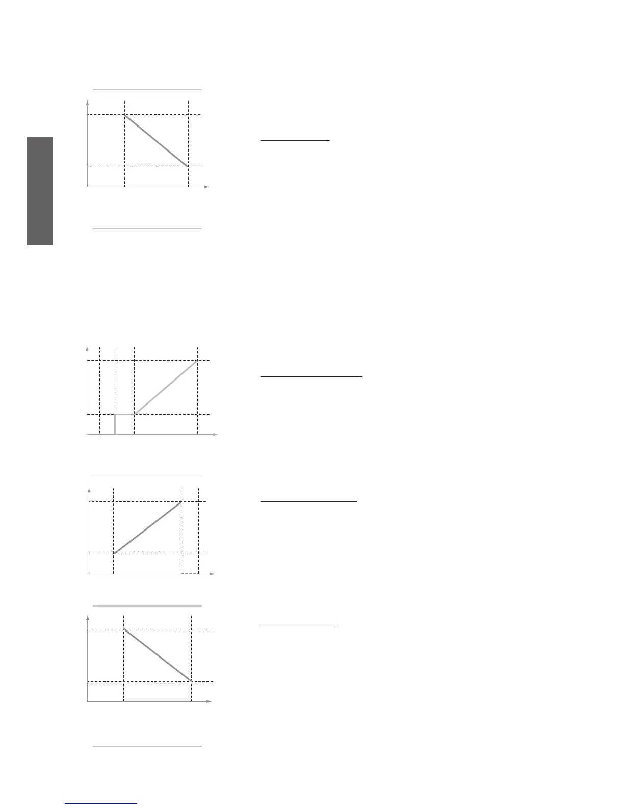
Activation time (cooling)
The activation time is not a set parameter, but rather the combination of two set parameters, that is, r08
and r09. When the temperature leaves the dead zone, the activation time is equal to r08, while at the end
of the differential r02 the activation time is equal to r09.
Inside the differential r02, the activation time varies linearly between r08 and r09.
This means that as the temperature moves away from the set point, the times are reduced and the espon-
se of the process becomes more dynamic.
- Deactivation delay at upper limit of r12 (if r06 = 4)
r10: The value set is used in the control algorithm (see timed outlet temperature control) as the maxi-
mum time (at the set point) for the deactivation of the compressors.
- Deactivation delay at lower limit of r12 (if r06 = 4)
r11: The value set for this parameter is used in the control algorithm (see timed outlet temperature
control) as the minimum time (at the end of the deactivation differential) for the deactivation of the
compressors.
Fig. 5.b.e
activation time
temperature
tempo
dead zone comp. act. differential
Fig. 5.b.f
deactivation time
temperature
tempo
compressor
stop compressors
deactivation differential
Fig. 5.b.g
activation time
temperature
tempo
Fig. 5.b.h
deactivation time
temperaturw
tempo
deactivation
differential
- Compressor deactivation differential (if r06 = 4)
r12: This represents the temperature differential for the deactivation of the compressors, according to the
procedure described in “Deactivation time”.
Deactivation time (cooling) Fig. 5.b.f
In the same way as for the activation time, the deactivation time also varies between a maximum value,
set for the parameter r10 and corresponding to the set point temperature, and a minimum, set for the
parameter r11 corresponding to the end of the differential for the deactivation of the compressors, set by
the parameter r12.
Below this value, the deactivation time will be equal to the minimum set until reaching the temperature
A04, after which all the compressors will be switched OFF, irrespective of the times. As the temperature
moves away from the set point, the response of the process becomes more dynamic.
Activation time (heating) Fig. 5.b.g
In heating mode, the activation time will ecrease as the deviation from the set point increases. The set
point is the heating set point r03 with the corresponding differential r04. The parameters for setting the
activation times are always r08 and r09.
Deactivation time (heating)
In heating mode, if the temperature rises above the set point, the deactivation time will decrease more
the further the temperature moves away from the heating set point r03. At the end of the differential r12,
the time will be the minimum set by parameter r11.

 Loading...


