riscaldamento bisogna assolutamente evitare che il ventilatore si fermi
mentre il riscaldamento è attivo, per evitare possibili rischi d’incendio.
Pertanto se H01=0 o 1, si deve selezionare H05=1.
- Ingresso digitale Estate/Inverno.
H06: Stabilisce se la selezione Estate/Inverno da ingresso digitale è
abilitata o meno (vedi parametri P08, P09, P10, P11, P12 e P13).
Lo stato aperto forza la macchina in funzionamento Estate,
viceversa, modalità Inverno.
D-IN Aperto = Estate
D-IN Chiuso = Inverno
- Ingresso digitale ON/OFF
H07: Stabilisce se la selezione ON/OFF da ingresso digitale è abilitata
o meno. Se la selezione è abilitata (H07= 1) lo stato “aperto” forza
la macchina a spegnersi mentre con lo stato “chiuso” la macchina
può essere spenta o accesa anche da tastiera.
- Configurazione rete µC
2
H08: Stabilisce la struttura della rete tLan.
0 = solo µC
2
1 = µC
2
+ valvola
2 = µC
2
+ exp.
3 = µC
2
+ exp. + valvola
- Abilitazione tastiera
H09: Permette di disabilitare la modifica dei parametri DIRECT e USER
da tastiera ma consente comunque la visualizzazione del valore
dei parametri. Vengono disabilitate anche le funzioni
abilitazione/disabilitazione Estate/Inverno e reset contatori.
Stato Tastiera:
0: disabilitata
1: abilitata (default)
- Indirizzo seriale
H10: Stabilisce l'indirizzo dello strumento per il collegamento seriale, tramite
scheda opzionale, ad un sistema di supervisione e/o teleassistenza.
- Selezione mappa uscite
H11: Questo parametro permette di associare arbitrariamente alcune
uscite digitali agli organi dell’unità.
H11= 0: standard (default); per unità con un compressore per circuito
(H04=0, 2).
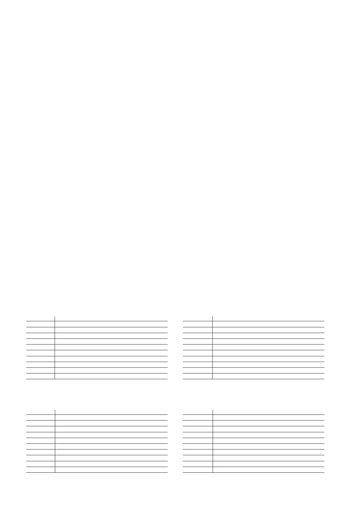
Uscite Associazione agli organi dell’unità
C1 Compressore 1
C2 Resistenza 1
C3 Pompa/(ventilatore) evaporatore (se unità aria/aria)
C4 Valvola inversione ciclo 1
C5 Allarme
C6 Compressore 2
C7 Resistenza 2
C8 Pompa condensazione/backup
C9 Valvola inversione ciclo 2
C10 Avviso
Tab 5.3
H11= 1: Per unità solo freddo bicompressore (H01=0, 2, 4, 7, 9, e
H04=1, 3, 5)
Uscite Associazione agli organi dell’unità
C1 Compressore 1
C2 Resistenza 1
C3 Pompa/(ventilatore) evaporatore (se unità aria/aria)
C4 Compressore 2 (o parzializzazione comp. 1)
C5 Allarme
C6 Compressore 3
C7 Resistenza 2
C8 Pompa condensazione/backup
C9 Compressore 4 (o parzializzazione comp. 2)
C10 Avviso
Tab.5.4
device, the fan must not be stopped while heating is active. This would
cause the risk of fire. Therefore, if H01=0 or 1, H05 must be set to 1.
- Cooling/heating digital input.
H06: Establishes whether the cooling/heating selection from digital
input is enabled. see parameters P08, P09, P10, P11, P12 and
P13). The open status places the unit in cooling operation,
vice-versa, in heating.
D-IN Open = Cooling
D-IN Closed = Heating
- ON/OFF digital input
H07: Establishes whether the ON/OFF selection from digital input is
enabled or disabled. If the selection is enabled (H07= 1), the
“open” status switches the unit Off, while in the “closed” status, the
unit may be OFF or ON, as controlled by the keypad.
- µC
2
network configuration
H08: Establishes the layout of the tLan network.
0 = µC
2
only
1 = µC
2
+ valve
2 = µC
2
+ exp.
3 = µC
2
+ exp. + valve
- Enable keypad
H09: Used to disable the modification of the DIRECT and USER
parameters from the keypad. The value of the parameters can
always be displayed. The enable/disable cooling, heating and
reset counter functions are also available.
Values:
0: keypad disabled
1: keypad enabled (default)
- Serial address
H10: Establishes the address of the instrument for the serial connection,
via an optional board, to a PC for supervision and/or telemaintenance.
- Selection map outputs
H11: This parameter is used to arbitrarily associate some digital
outputs to the devices on the unit.
H11= 0: standard (default); for units with one compressor per circuit
(H04=0, 2).
Outputs Associated device
C1 Compressor 1
C2 Heater 1
C3 Pump/evaporator (fan) (on air/air units)
C4 Reversing valve 1
C5 Alarm
C6 Compressor 2
C7 Heater 2
C8 Condenser pump/backup
C9 Reversing valve 2
C10 Warning
Tab 5.3
H11= 1: For cooling only units with two compressors (H01=0, 2, 4, 7, 9
and H04=1, 3, 5)
Outputs Associated device
C1 Compressor 1
C2 Heater 1
C3 Pump/evaporator (fan) (on air/air units)
C4 Compressor 2 (or capacity control comp. 1)
C5 Alarm
C6 Compressor 3
C7 Heater 2
C8 Condenser pump/backup
C9 Compressor 4 (or capacity control comp. 2)
C10 Warning
Tab 5.4
54
µC
2
- cod. +030220420 - rel. 2.0 - 18.10.04

 Loading...


