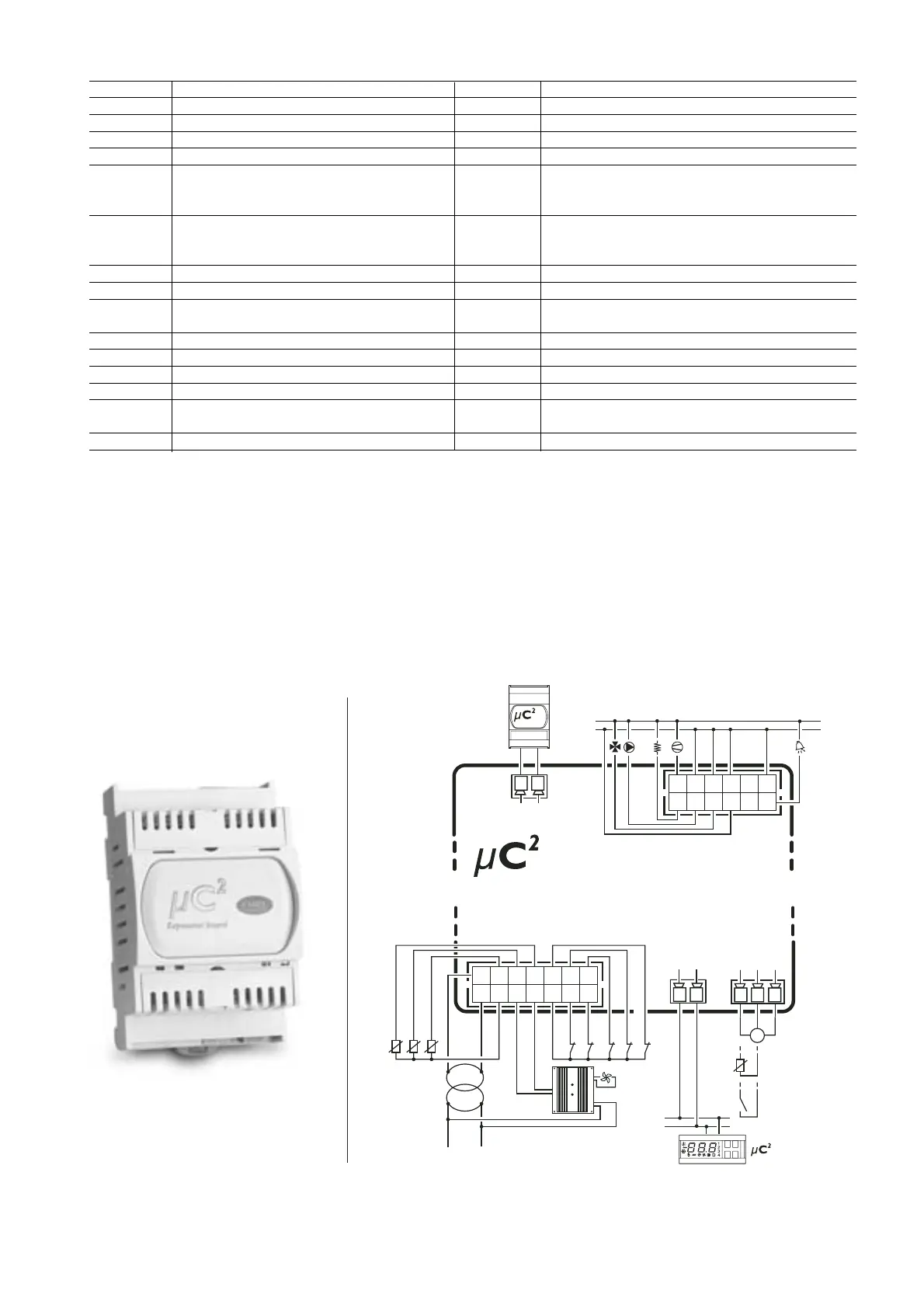
7.2 Scheda espansione
Questo dispositivo permette al µC
2
di gestire il secondo circuito
frigorifero di Chiller, Pompe di Calore e motocondensanti fino a 4
compressori ermetici.
Di seguito è riportato lo schema di collegamento della scheda
espansione per µC
2
, codice MCH200002*.
7.2 Expansion card
This device allows the µC
2
to manage the second refrigerant circuit on
chillers, heat pumps and condensing units with up to 4 hermetic
compressors.
The following figure shows the connection diagram for the µC
2
expansion card, code MCH200002*.
71
µC
2
- cod. +030220420 - rel. 2.0 - 18.10.04
I/O Layout
µC
2
Description Expansion Description
B1 Control probe (Evaporator inlet/ambient) B5 Sonda uscita in comune ai 2 evaporatori (solo con 2 circuiti)
B2 Protection probe (evaporator outlet/outlet) B6 Sonda di protezione (uscita 2° evaporatore) circuito 2
B3 Condenser/outside temperature probe B7 Sonda di temperatura 2° condensatore
B4 (universal) Condenser pressure probe B8 (universal) Sonda pressione 2° condensatore
ID1 Flow switch – thermal overload circuit 1 – ID6 Flow switch – thermal overload circuit 2 –
cooling/heating – end defrost circuit 1 – step 1 – end defrost circuit 2 – step 4
condensing unit – second set point condensing unit – second set point
ID2 Flow switch – thermal overload 1 circuit – ID7 Flow switch – thermal overload circuit 2 –
cooling/heating – end defrost circuit 1 – step 2 - end defrost circuit 2 – step 4
condensing unit – second set point condensing unit– second set point
ID3 High pressure circuit 1 ID8 High pressure circuit 2
ID4 Low pressure circuit 1 ID9 Low pressure circuit 2
ID5 Remote ON/OFF – reverse cycle condensing unit ID10
if reversible
Y1 Ramp circuit 1 (condenser) Y2 Ramp circuit 2 (condenser)
C1/2-NO1 Compressor 1 C6/7-NO6 Compressor 3 (1 in 2nd circuit)
C1/2-NO2 Heater or reversing valve in 1st circuit C6/7-NO7 Heater or reversing valve in 2nd circuit
C3/4-NO3 Fan 1/evaporator pump C8/9-NO8 Fan 2/condenser pump/backup
C3/4-NO4 Compressor 2 (capacity-control compressor 1) C8/9-NO9 Compressor 4 (capacity-control compressor 2) or reversing
valve circuit 1 or reversing valve circuit 2
C5-NO5 Alarm or reversing valve C10-N010 Warning or reversing valve circuit 2
Tab. 7.1
*= Any of the options for P08 can be selected (see Tab. 5.11)
**= Any of the options for P08 can be selected, except for E/I and E/I delay.
cond. probe
low press.
multi funct.
multi funct.
high press.