P05= 4: alta e bassa pressione in manuale, antigelo (bassa
temperatura) in automatico
P05= 5: alta e bassa pressione in manuale al terzo intervento in
un’ora*, antigelo (bassa temperatura) in automatico
P05= 6: alta e bassa pressione in manuale al terzo intervento in
un’ora*, antigelo (bassa temperatura) in manuale
Tab. 5.9
*gli allarmi di alta e bassa pressione sono gestiti allo stesso modo sia
per i trasduttori sia per i pressostati (ingresso digitale); se l’unità è in
stand-by il conteggio (3 volte in un’ora) viene resettato.
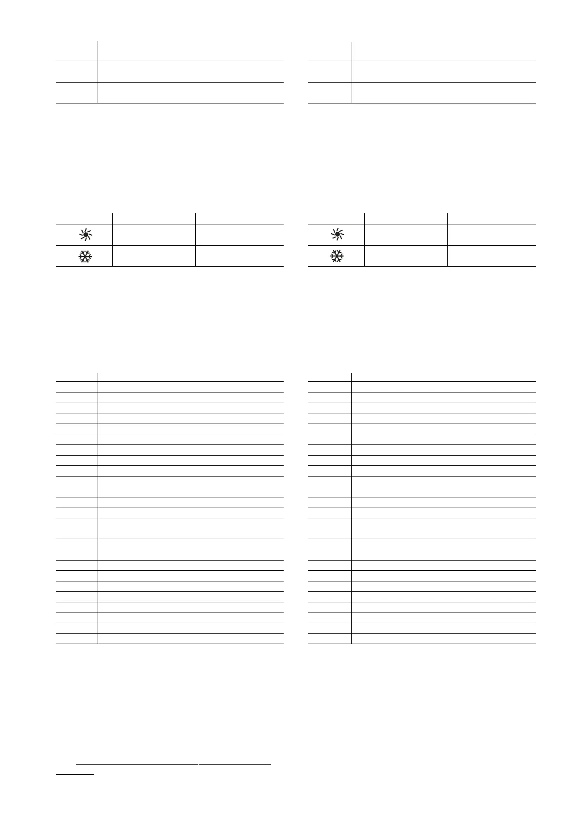
- Logica Estate/Inverno
P06: Con tale parametro impostato ad 1 si inverte anche la logica di
funzionamento della selezione Estate/Inverno (sia da tastiera che
da telecomando e da ingresso digitale).
Simbolo P06=0 P06=1
Estate (Chiller) Inverno (pompa calore)
Inverno (pompa Estate (Chiller)
calore)
Tab.5.10
- Allarme di bassa pressione con sonde di pressione
P07: P07=0: tale funzione viene disabilitata.
P07=1: se in modalità pompa calore la pressione dell’evaporatore
(scambiatore esterno) è inferiore ad 1 bar (e se abilitata la presenza
della sonda di condensazione in pressione) viene attivato l’allarme
di bassa pressione (mantenendo comunque l’eventuale ritardo P03).
-Selezione ingresso digitale ID1
P08= 0: nessuno
P08= 1: flussostato con ripristino manuale (normalmente chiuso)
P08= 2: flussostato con ripristino automatico (N.C.)
P08= 3: termico generale con ripristino manuale (N.C.)
P08= 4: termico generale con ripristino automatico (N.C.)
P08= 5: termico circuito 1 con ripristino manuale (N.C.)
P08= 6: termico circuito 1 con ripristino automatico (N.C.)
P08= 7: termico circuito 2 con ripristino manuale (N.C.)
P08= 8: termico circuito 2 con ripristino automatico (N.C.)
P08= 9: Estate/Inverno (aperto = Estate, chiuso = Inverno)
P08= 10: Estate/Inverno con ritardi d12 e d13 (aperto = Estate,
chiuso = Inverno)
P08= 11: segnalazione allarme con ripristino manuale (N.C.)
P08= 12: segnalazione allarme con ripristino automatico (N.C.)
P08= 13: secondo set-poit da contatto esterno (sia estivo che
invernale), (normalmente aperto)
P08= 14: secondo Set-Point estivo da contatto esterno ed
invernale da fascia oraria (N.A.)
P08= 15: fine defrost da contatto esterno circuito 1 (N.C.)
P08= 16: fine defrost da contatto esterno circuito 2 (N.C.)
P08= 17: inizio defrost da contatto esterno circuito 1 (N.C.)
P08= 18: inizio defrost da contatto esterno circuito 2 (N.C.)
P08= 19: step 1 motocondensante (N.A.)
P08= 20: step 2 motocondensante (N.A.)
P08= 21: step 3 motocondensante (N.A.)
P08= 22: step 4 motocondensante (N.A.)
Tab. 5.11
nota 1: nel caso P08 sia impostato a 10, il cambio di stato considera i
tempi d12 e d13, e rispetta i tempi di protezione dei compressori, sia
esso dipeso dall'ingresso digitale, sia da tastiera.
nota 2: nel caso l'ingresso digitale venga utilizzato per l' ON/OFF od il
cambio stagione, la tastiera viene disabilitata inibita a tali funzioni.
- Selezione ingressi digitali ID2, ID6, ID7, ID10
P09, P10, P11, P12: Configurazione rispettivamente degli ingressi digitali
ID2, ID6, ID7 e ID10 (come da tabella sopra per ingresso digitale ID1).
Nota: Non è possibile impostare estate/in
verno (9,10) su P10, P11,
P12, e P14.
P05= 4: high and low pressure manual, antifreeze (low
temperature) automatic
P05= 5: high and low pressure manual after the third activation in
one hour*, antifreeze (low temperature) automatic
P05= 6: high and low pressure manual after the third activation in
one hour*, antifreeze (low temperature) manual
Tab. 5.9
* the high and low pressure alarms are managed in the same way both
for the transducers and the pressure switches (digital input); if the unit
is in standby the count (3 times in one hour) is reset.
- Cooling/Heating logic
P06: If this parameter is set to 1, the operating logic of the
Cooling/Heating logic is reversed (from the keypad, the remote
control and the digital input).
Symbol P06=0 P06=1
Cooling (Chiller) Heating (heat pump)
Heating
(heat pump) Cooling (Chiller)
Tab. 5.10
- Low pressure alarm with pressure probes
P07: P07=0: this function is disabled.
P07=1: if in heat pump mode the evaporator (external exchanger)
pressure is less than 1 bar (and if the presence of the condenser
pressure probe is enabled), the low pressure alarm is activated
(while still considering the delay P03).
- Select digital input ID1
P08= 0: none
P08= 1: flow switch with manual reset (normally closed)
P08= 2: flow switch with automatic reset (NC)
P08= 3: general thermal overload with manual reset (NC)
P08= 4: general thermal overload with automatic reset (NC)
P08= 5: thermal overload circuit 1 with manual reset (NC)
P08= 6: thermal overload circuit 1 with automatic reset (NC)
P08= 7: thermal overload circuit 2 with manual reset (NC)
P08= 8: thermal overload circuit 2 with automatic reset (NC)
P08= 9: cooling/heating (open = Cooling, closed = Heating)
P08= 10: cooling/heating with delays d12 and d13 (open =
Cooling, closed = Heating)
P08= 11: alarm signal with manual reset (NC)
P08= 12: alarm signal with automatic reset (NC)
P08= 13: second set point from external contact (cooling
and heating), (normally open)
P08= 14: second cooling set point from external contact and
heating from time band (NO)
P08= 15: end defrost from external contact circuit 1 (NC)
P08= 16: end defrost from external contact circuit 2 (NC)
P08= 17: start defrost from external contact circuit 1 (NC)
P08= 18: start defrost from external contact circuit 2 (NC)
P08= 19: condenser step 1 (NO)
P08= 20: condenser step 2 (NO)
P08= 21: condenser step 3 (NO)
P08= 22: condenser step 4 (NO)
Tab. 5.11
note 1: if P08 is set to 10, the change in state considers the times d12
and d13, and respects the compressor protection times, both from the
digital input and the keypad.
note 2: if the digital input is used to switch the unit ON/OFF or change
the operating mode, these functions are disabled on the keypad.
- Select digital inputs ID2,ID6,ID7,ID10
P09, P10, P11, P12: Configuration of digital inputs ID2, ID6, ID7 and
ID10 respectively (as per the above table for digital input ID1).
Note: cooling/heating (9,10) cannot be set on P10, P11, P12, and P14.
57
µC
2
- cod. +030220420 - rel. 2.0 - 18.10.04
 Loading...


