Caratteristiche funzionali
Risoluzione ingressi analogici Sonde di temperatura:
intervallo -40T80 °C, 0.1 °C
Errore di misura in temperatura Intervallo -20T20 °C, ±0.5 °C
(escluso sonda)
Intervallo -40T80 °C, ±1.5 °C
(escluso sonda)
Errore di misura in pressione L’errore % in tensione con range di
ingresso 0,5...4,5 è ± 2% (escluso
sonda).
L’errore sul valore convertito può
variare a seconda dell’ impostazione
dei parametri /9, /10, /11, /12
Tab. 10.2
Functional characteristics
Resolution of the Temperature probes:
analogue inputs Range -40T80 °C, 0.1 °C
Temperature measurement Range -20T20 °C, ±0.5 °C
error (excluding probe)
Range -40T80 °C, ±1.5°C
(excluding probe)
Pressure measurement error The % error with a voltage reading
with a range of input from 0.5 to 4.5
is ± 2% (excluding probe).
The error in the converted value may
vary according to the settings of
parameters /9, /10, /11, /12
Tab.10. 2
86
µC
2
- cod. +030220420 - rel. 2.0 - 18.10.04
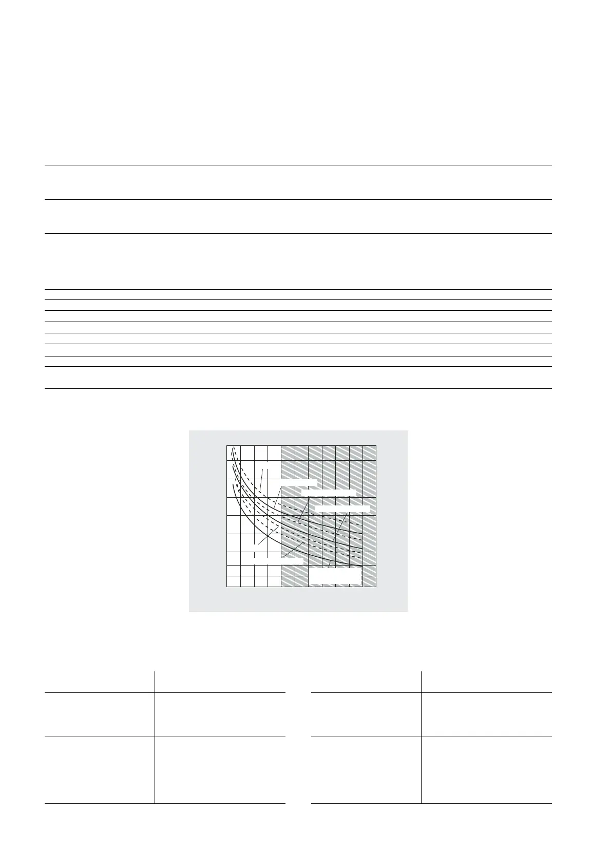
Fig. 10.1
Relays Max current at 250 Vac: EN60730: resistive: 3A, Inductive: 2A cos
ϕ
=0.4 60,000 cycles
UL: Resistive: 3A, 1 FLA, 6 LRA cos
ϕ
=0.4 30,000 cycles
For further information refer to the characteristics shown in Figure 6.1
Minimum interval between communications (each relay): 12 s (the manufacturer of the unit that the
device is integrated into must ensure the correct configuration so as to respond to this specification)
Type of microswitching: 1 C
Insulation between relays in group A: functional
Insulation between the relays in group A and the very low voltage parts: reinforced
Insulation between relays in group A and the signal relays: primary
Insulation between the signal relays and the very low voltage parts: reinforced
Insulation between the relays and the front panel: reinforced
Digital inputs ID1-ID5, IDB4 Electrical standard: voltage-free contacts
Closing current to earth: 5 mA
Maximum closing resistance: 50
Ω
Analogue inputs B1, B2, B3, B4: NTC CAREL temperature probes (10 k
Ω
at 25 °C)
The response time depends on the component used, typical value 90 s
B4: NTC temp. probes (10 k
Ω
at 25 °C) or CAREL 0 to 5 V ratiometric pressure probes SPKT00**R*
Fan output Control signal for CAREL modules MCHRTF****, CONVONOFF* and CONV0/10A*
Phase width modulation (settable width) or modulation of the duty cycle
No-load voltage: 5V ± 10%
Short-circuit current: 30 mA
Minimum output load: 1 k
Ω
Front panel index of protection IP055
Storage conditions -10T70 °C – humidity 80 % rH non-condensing
Operating conditions -10T55 °C – humidity <90 % rH non-condensing
Degree of pollution Normal
Cat. of resist. to heat and fire D (RU94 V0)
PTI of the insulating materials All the insulating materials have PTI
≥
250 V
Software class and structure A
Period of electric stress across Long
insulating parts
Tab.10.1
Homologations: CE/RU (File: EI98839 sez. 16)
Note: all the relays must have the common terminals (C1/2, C3/4, C6/7, C8/9) connected together.