4.6 Installazione del terminale utente
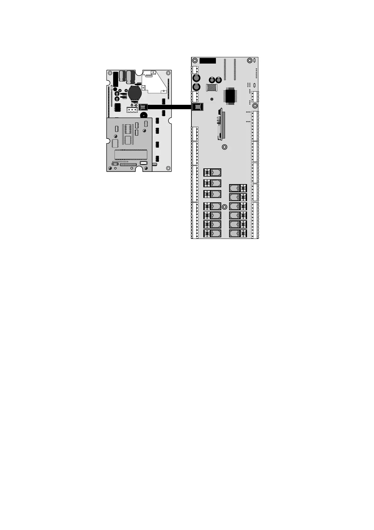
La connessione tra terminale utente e scheda base viene effettuata
tramite cavo telefonico a 6 vie fornito da CAREL.
Per effettuare il collegamento basta inserire il connettore telefonico nel
morsetto J19 della scheda base e nel morsetto B del terminale. Inserire
a fondo il connettore nel morsetto finché non scatta il serraggio.
Per estrarre il connettore basta premere leggermente sul fermo in
plastica sporgente e sfilare il cavo.
La scheda base può funzionare anche senza terminale; non scollega-
re e poi ricollegare il terminale alla scheda base senza aver atteso
circa 5 secondi (qualora l’operazione venga eseguita a macchina
accesa).
Installazione dei terminali da parete/pannello (cod. PCOT00****):
Questo tipo di terminale è stato disegnato per il montaggio a pannello
e a parete. La dima di foratura, nel caso di montaggio a pannello, deve
avere le dimensioni di 167x108 mm.
Per l’installazione fare attenzione alle seguenti istruzioni:
• svitare le due viti poste sul coperchio posteriore del terminale
e sfilare il coperchio;
• appoggiare il frontale sulla parte anteriore del pannello;
• inserire il coperchio dalla parte posteriore facendo coincidere i due
fori con i due prigionieri posizionati nel coperchio frontale;
• riavvitare le viti.
Lo spessore massimo del pannello è di 6 mm. Effettuare quindi i previ-
sti collegamento elettrici. Il montaggio a parete prevede l’utilizzo del-
l’apposita staffa di fissaggio e di una scatola da parete standard a 3
moduli per interruttori al fine di consentire il passaggio dei cavi. Fissare
la staffa alla parete, utilizzando la vite; effettuare infine i previsti colle-
gamenti elettrici ed incastrare il dorso dello strumento alla staffa.
Collegamenti elettrici
Collegare il cavo telefonico (cod. S90CONN00*) proveniente dalla
scheda di potenza (cod. PCOB*) nell’apposita presa. Il modello con
display grafico (cod. PCOT00OGH0) è provvisto di un’ulteriore morset-
tiera a vite.
4.6 Installation of the user terminal
The connection between the user terminal and main board is made
using a 6-way telephone-type cable supplied by CAREL.
To make the connection simply insert the telephone-type connector in
terminal J19 on the main board and in terminal B in the user terminal.
Fully insert the connector into the terminal until the lock snaps into
place.To remove the connector press lightly on the protruding plastic
stop and pull out the cable.
The main board can also function without the terminal; do not discon-
nect and then re-connect the terminal to the main board without
first waiting around 5 seconds (if the operations are performed while
the machine is on).
Wall/panel mounting of the terminal (code PCOT00****):
This type of terminal has been designed for panel- and wall-mounting.
The drilling template, in the case of panel-mounting, must have dimen-
sions of 167x108 mm.
During installation carefully note the following instructions :
• unscrew the two screws on the rear cover of the terminal and
remove the cover;
• rest the front cover on the rear part of the panel;
• insert the rear cover, making sure the two holes correspond
to the two screw studs on the front cover;
• tighten the screws.
The maximum panel thickness allowed is 6 mm. Perform the required
electrical connections.Wall-mounting requires the use of a special
mounting bracket and a standard 3-module switchbox in order to allow
the passage of the cables. Fasten the bracket to the wall , using the
screws; finally, perform the required electrical connections and clip the
rear of the instrument onto the bracket.
Electrical connections
Connect the telephone-type cable (code S90CONN00*) from the power
board (code PCOB*) into the relative socket.The model with graphic
display (code PCOT00OGH0) is fitted with an extra screw-in terminal
block.
16

 Loading...


