6.4 Connessioni elettriche pLAN
La connessione tra schede in pLAN si effettua usando un cavo scher-
mato AWG20/22 costituito da una coppia twistata e lo schermo. Le
schede vanno collegate in parallelo facendo riferimento al morsetto J11.
ATTENZIONE rispettare le polarità di rete: l’RX/TX+ di una scheda
deve essere collegato al RX/TX+ delle altre schede ; la stessa cosa
per RX/TX-.
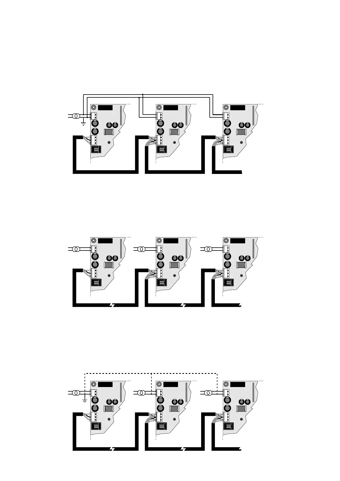
Di seguito viene rappresentato lo schema di più schede collegate in
rete pLAN alimentate dallo stesso trasformatore: (tipica applicazione di
più schede collegate all’interno di uno stesso quadro elettrico).
Di seguito viene rappresentato lo schema di più schede collegate in
rete pLAN alimentate da trasformatori diversi (con il G0 non connesso
a terra): (tipica applicazione di più schede che fanno parte di quadri
elettrici diversi).
Attenzione: Con questa configurazione è necessario installare trasfor-
matori di sicurezza (doppio isolamento)
Di seguito viene rappresentato lo schema di più schede collegate in
rete pLAN alimentate da trasformatori diversi con unico riferimento di
terra: (tipica applicazione di più schede che fanno parte di quadri
elettrici diversi)
Attenzione: Il collegamento a terra deve essere effettuato sulla stessa
linea di terra (stesso pozzetto di terra per tutte le schede pCO).
6.4 pLAN electrical connections
Connection between boards in a pLAN network is carried out using an
AWG20/22 shielded cable, made up of a twisted pair plus shield.The
boards are connected in parallel, with terminal J11 as the reference.
Pay ATTENTION to the network polarity: RX/TX+ on one board must
be connected to RX/TX+ on the other boards; the same is true for
RX/TX-.
The following is a diagram of a number of boards connected in a pLAN
network and powered by the same transformer: (typical application: a
number of boards connected inside the same electrical panel).
The following is a diagram of a number of boards connected in a pLAN
network and powered by different transformers (with G0 not earthed):
(typical application: a number of boards inside different electrical
panels.
Attention: With this configuration a safety transformer (double insulated)
must be installed
The following is a diagram of a number of boards connected in a pLAN
network and powered by different transformers with the same earth
reference: (typical application: a number of boards inside different
electrical panels)
Attention: The earth connection must be made to the same earth line
(same earth plate for all the pCO boards).
22

 Loading...


