11. Montaggio terminale utente
11.1 Montaggio a pannello
PCOT*
PCOI*
11.2 Montaggio a parete
11. User Terminal mounting
11.1 Panel mounting
PCOT*
PCOI*
11.2 Wall-mounting
37
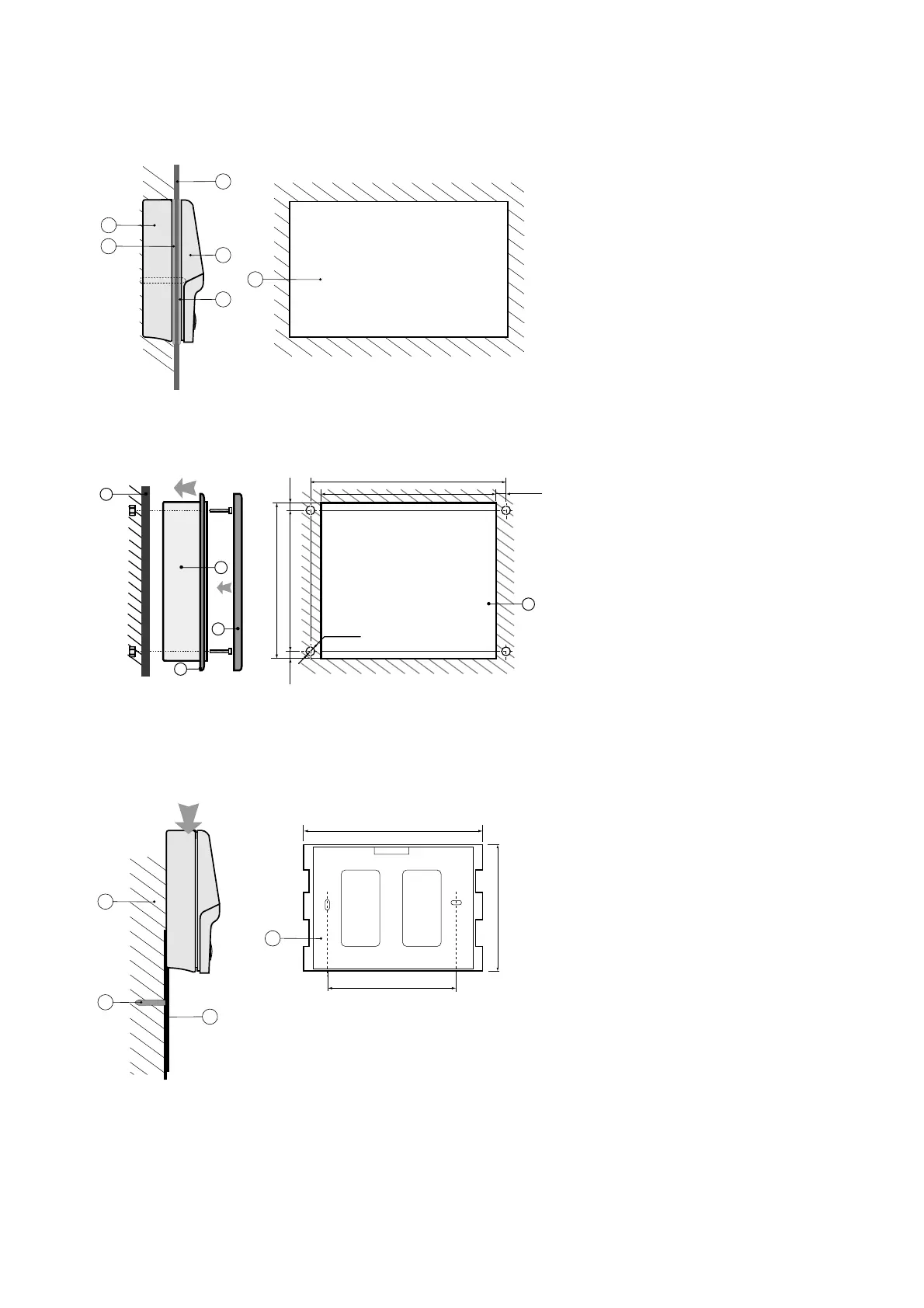
Riferimenti / Legenda (Fig. 45)
1. Coperchio posteriore / Rear cover
2. Pannello / Panel
3. Coperchio anteriore / Front cover
4. Dime di foratura (tolleranza finestra: -0,5÷ +1 mm
sulle dimensioni indicate) / Drilling template
(tolerance: -0.5÷ +1 mm on the indicated dimensions)
5. Guarnizione per coperchio posteriore / Rear cover gasket
6. Guarnizione per coperchio anteriore / Front cover gasket
Fig. 45
Riferimenti / Legenda (Fig. 46)
1. Cornice esterna / External frame
2. Pannello / Panel
3. Terminale / Terminal
4. Dime di foratura (tolleranza finestra: -0,5÷ +0,5 mm
Drilling template (tolerance: -0.5÷+0.5 mm)
5. Guarnizione frontale / Front cover gasket
Avvertenza: lo spessore massimo del pannello deve essere
di 6 mm.
Warning: the maximum thickness of the panel is 6 mm.
Il montaggio a parete prevede l’utilizzo di un’apposita
staffa di fissaggio e di una scatola da parete standard a 3
moduli per interruttori al fine di consentire il passaggio
dei cavi. Fissare la staffa (1) alla parete (3) utilizzando la
vite (2); incastrare il dorso dello strumento alla staffa.
Wall-mounting requires the use of a special mounting
bracket and a standard 3-module switchbox for the
passage of the cables. Fasten the bracket (1) to the wall
(3) using the screws (2); clip the rear of the instrument
onto the bracket.
Fig. 47

 Loading...


