Avvertenza: le quote riportate sopra sono espresse in mm.
10.3 Scheda base PCOB*
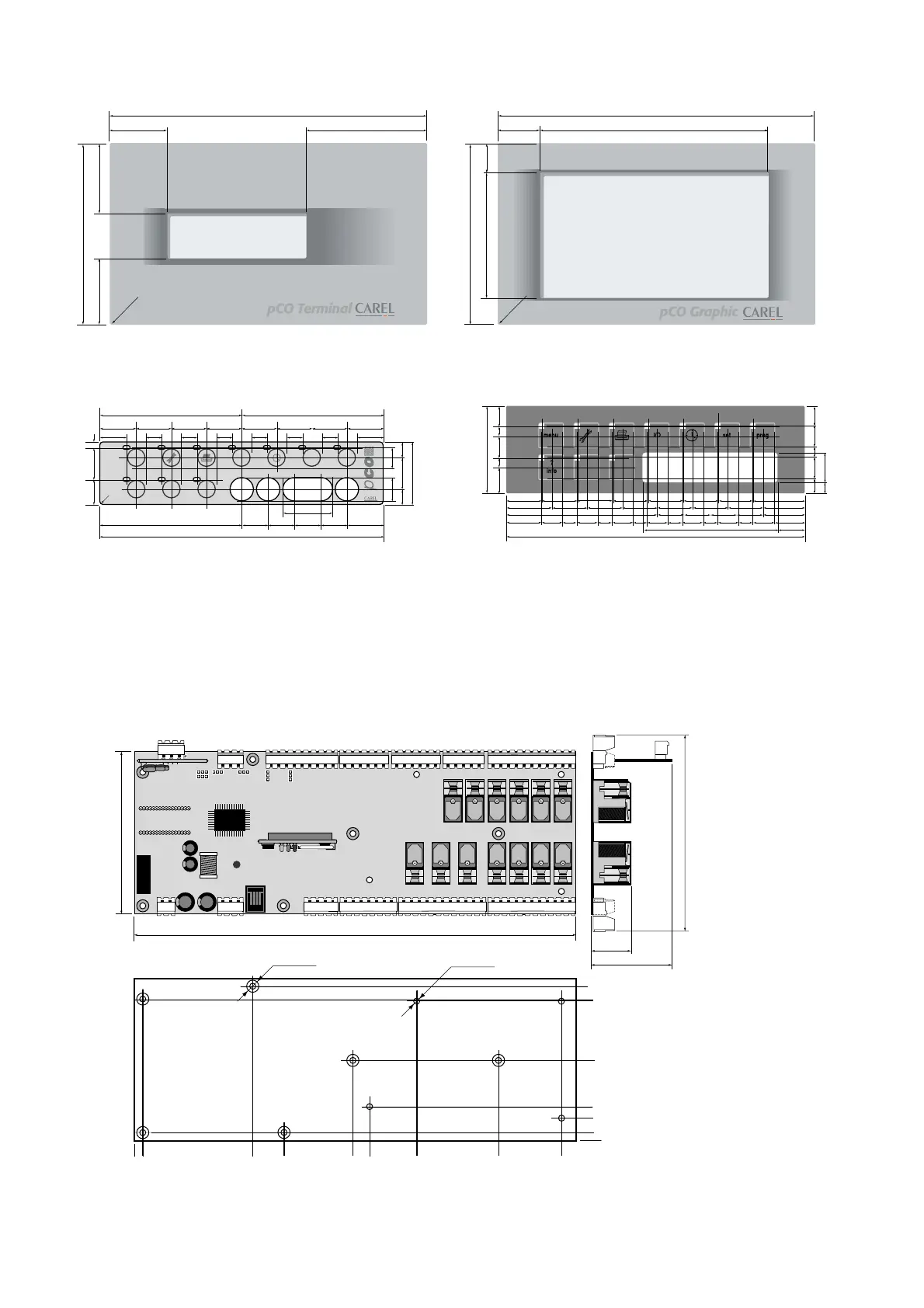
In Figura 44 sono indicati i fori di fissaggio e le dimensioni della scheda
base per il montaggio a quadro. I fori contraddistinti da una coroncina
sono metallizzati e su questi vanno fissate le torrette metalliche colle-
gate a loro volta alla terra del quadro.
Avvertenza: prima di eseguire ogni collegamento elettrico leggere i
consigli a pagina seguente e le note a pag.14.
Warning: all dimensions are expressed in mm.
10.3 Main board PCOB*
Figure 44 shows the mounting holes and the dimensions of main board
for mounting in electrical panels.The holes marked with an outer ring
are metal-plated and are used for attaching the metal turrets, which in
turn are connected to the earth of the electrical panel.
Warning: before performing any electrical connection see the following
page and the notes on page 14.
36
Policarbonato del terminale PCOI* con LCD 4 x20
Polycarbonate cover for the pCO terminal I* with 4 x20 LCD
Policarbonato del terminale PCOIPGL0 grafico 240 x 128
Polycarbonate cover for the pCO IPGL0 240 x 128 graphic terminal
Policarbonato della tastiera del terminale PCOT*
Polycarbonate keypad cover for the pCO terminal T*
Policarbonato della tastiera del terminale PCOI
Polycarbonate keypad cover for the pCO terminal I*
Figura 44: Dimensioni e fori di
fissaggio scheda base (in mm)
Figure 44: Dimensions and mounting
holes for the main board (in mm)

 Loading...


