Architettura Hardware
L’architettura hardware è così definita:
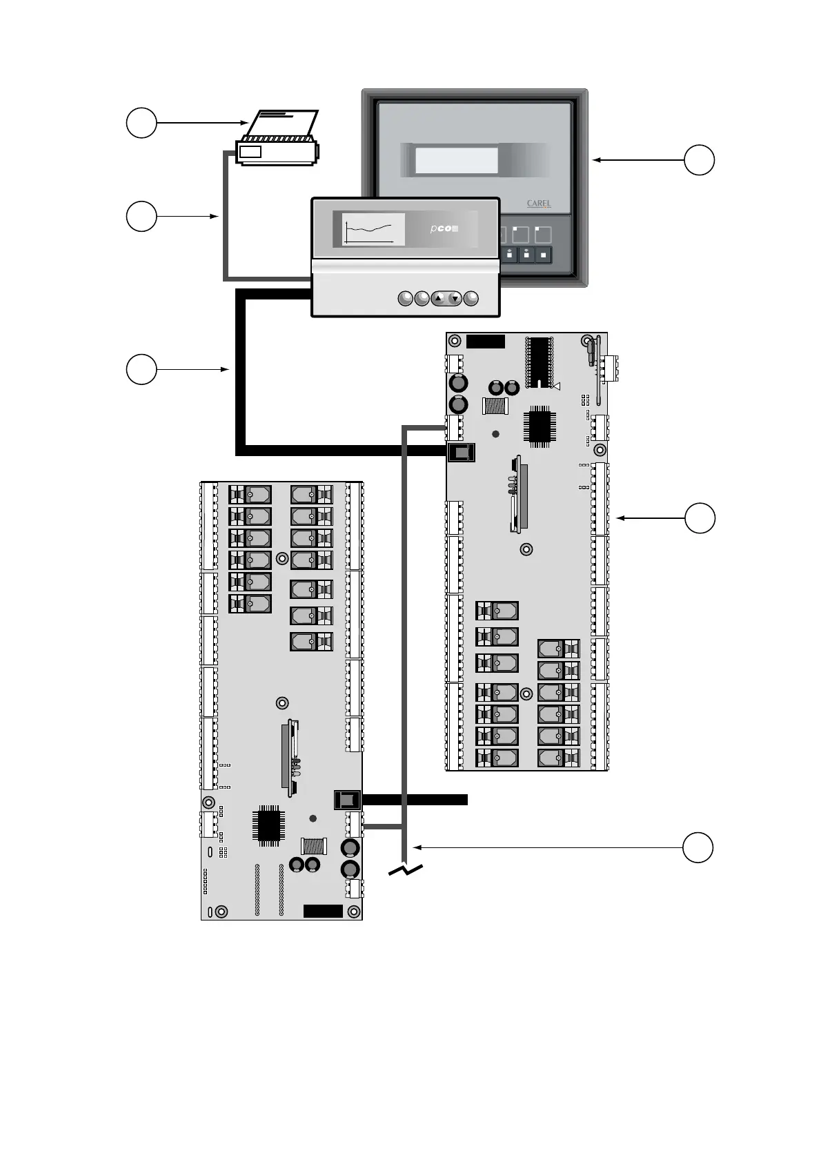
1. Terminale utente con tastiera, display e LED di segnalazione.
2. Scheda Base con microprocessore, EPROM con il programma
applicativo, morsetti ingresso/uscita.
3. Cavo di collegamento tra terminale e scheda base.
4. Cavo di collegamento tra terminale e stampante seriale
(a cura del cliente).
5. Stampante seriale (a cura del cliente).
6. Cavo AWG20/22 per connessione in pLAN tra più schede pCO.
Hardware Structure
The hardware structure is the following:
1. User terminal with keypad, display and signal LEDs.
2. Main board with microprocessor, EPROM containing the
application program, input/output terminals.
3. Cable for connecting the terminal and the main board.
4. Cable for connecting the terminal and a serial printer
(supplied by the customer).
5. Serial printer (supplied by the customer).
6. AWG20/22 cable for pLAN connection between a number
of pCO boards
3

 Loading...


