21
ENG
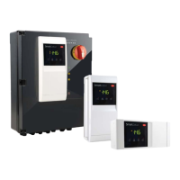
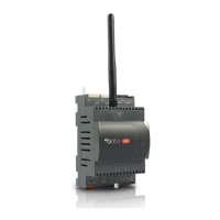
“SmartCella 3PH” +0500119IE - rel. 1.3 - 21.11.2019
3. PARAMETER TABLE
Symbol Code Parameter UOM Type Min. Max. Def.
Pw Password - C 0 200 22
/2 Probe measurement stability - C 1 15 4
/3 Probe display stability - C 0 15 0
/4 Virtual probe composition - C 0 100 0
/5 Temperature unit of measure (0: °C .1: °F) fl ag C 0 1 0
/6 Display decimal point
0: with tenths of a degree
1: without tenths of a degree
fl a g C 0 1 0
/tI Display on user terminal
1: virtual probe
2: probe 1
3: probe 2
4: probe 3
5: probe 4
6: reserved
7: set point
-C171
/tE Reading on remote display
0: remote terminal not connected
1: virtual probe
2: probe 1
3: probe 2
4: probe 3
5: probe 4
6: reserved
-C060
/P Type of probe
0: Standard NTC with range -50T90°C
1: NTC enhanced with range -40T150°C
2: Standard PTC with range -50T150°C
-C020
/A2 Probe 2 confi guration (S2)
0: not connected
1: product (display only)
2: defrost
3: condenser
4: frost protection
-C042
/A3 Probe 3 confi guration (S3/DI1) As for /A2 - C 0 4 0
/A4 Probe 4 confi guration (S4/DI2) As for /A2 - C 0 4 0
/A5 Probe 5 confi guration (S5/ID3) As for /A2 - C 0 4 0
/c1 Probe 1 calibration °C/°F C -20 20 0.0
/c2 Probe 2 calibration °C/°F C -20 20 0.0
/c3 Probe 3 calibration °C/°F C -20 20 0.0
/c4 Probe 4 calibration °C/°F C -20 20 0.0
/c5 Probe 5 calibration °C/°F C -20 20 0.0
St Set point °C/°F F r1 r2 0.0
rd Diff erential °C/°F F 0.1 20 2.0
rn Neutral zone °C/°F C 0.0 60 4.0
rr Reverse diff erential °C/°F C 0.1 20 2.0
r1 Minimum set point °C/°F C -50 r2 -50
r2 Maximum set point °C/°F C r1 200 60
r3 Operating mode
0: Direct with defrost control (cooling)
1: Direct (cooling)
2: Reverse (heating)
fl a g C 0 2 0
r4 Automatic night-time set point variation °C/°F C -20 20 3.0
r5 Enable temperature monitoring
0: disabled, 1: enabled
fl a g C 0 1 0
rt Duration of current max and min temperature monitoring session ore F 0 999 -
rH Maximum temperature read °C/°F F - - -
rL Minimum temperature read °C/°F F - - -
c0 Compressor, fan and AUX start delay at start-up min C 0 15 0
c1 Minimum time between successive compressor starts min C 0 15 0
c2 Minimum compressor off time min C 0 15 0
c3 Minimum compressor on time min C 0 15 0
c4 Compressor running time with duty setting min C 0 100 0
cc Continuous cycle duration ore C 0 15 0
c6 Low temperature alarm bypass time after continuous cycle ore C 0 250 2
c7 Maximum pump down time (PD)
0= pump down disabled
s C 0 900 0
c9 Autostart in pump down
0= disabled
1= pump down whenever closing pump down valve & following low pressure switch activation
if there is no cooling request
fl agC010
c10 Pump down by time or pressure
0: Pump down by pressure
1: Pump down by time
fl a g C 0 1 0
c11 Second compressor start delay s C 0 250 4
 Loading...