BT2 user manual - H-5911-9004-02-B Page | 101
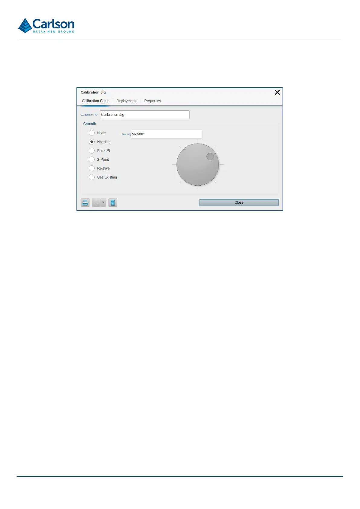
The list shows the Name of the alignment, followed by the Azimuth that has been manually input or computed.
To edit an alignment in the list, tap on the appropriate alignment to open the Alignment Details window. Edit the
details as required.
Note that if the heading is edited, all data collected using the selected alignment will be affected by this edit. Each
deployment will rotate around its collar position by the number of degrees by which the heading has changed.
14.2 Hole
Each Hole in a project has its own element in the Project tab. There may be multiple Holes in a Project and they
may be setup in advance of field operations.
The Hole may have one Planned and one or more Deployment elements nested beneath it.
• The Hole Visible / invisible button toggles all these elements on and off in the 3D View.
• The Hole Zoom button positions the extents of all these elements within the 3D View.
• The Hole Export button exports data from all these elements.
Tap the Hole Details button to open the Hole Details window. The Hole Details window has four tabs, described
below.
14.2.1 Hole Setup tab
The Hole Setup tab provides controls to configure the hole.
Figure 108 Alignment Details