BT2 user manual - H-5911-9004-02-B Page | 102
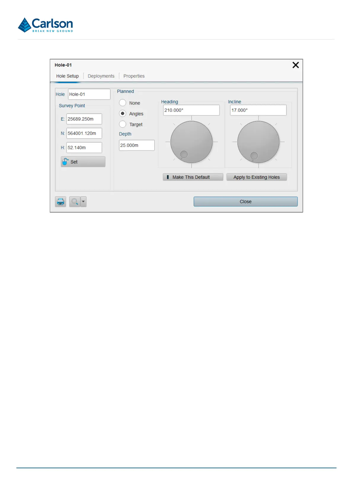
Enter a name for the hole in the Hole text field.
Enter the collar coordinates in the Survey Point text fields.
The Planned frame enables the setup of planned or ‘design’ hole properties. A surveyed deployment can be
compared with the planned hole to establish the deviation along the length of the surveyed hole.
One Planned hole can be set up for each Hole in a project. The settings are mirrored in the Deployment Details
window > Planned tab (see section 14.3.1).
The Planned hole can be set up using manually entered angles, or by entering coordinates for the end of the hole.
Use the radio buttons to select between these options.
• None: no Planned Hole is attached to the selected Hole.
• Angles: enter a Depth together with Heading angle and an Incline angle to establish the Planned Hole.
• Target: enter the X,Y,Z coordinates of the end of the hole to establish the Planned Hole. The Depth is
adjusted automatically.
To use the same planned hole values for holes which are created subsequently within the active project, tap Make
this default. If a new hole is created, these planned hole values are applied when the Angles or Target radio
buttons are selected.
To apply the same planned hole values to all holes which already exist in the active project, tap Apply to existing
holes.
14.2.2 Deployments tab
The Deployments tab lists the Boretrak2 deployments which have been carried out from the selected Hole.
Figure 109 Hole > Hole Setup