BT2 user manual - H-5911-9004-02-B Page | 21
The probe must be absolutely stable for the alignment to be successful.
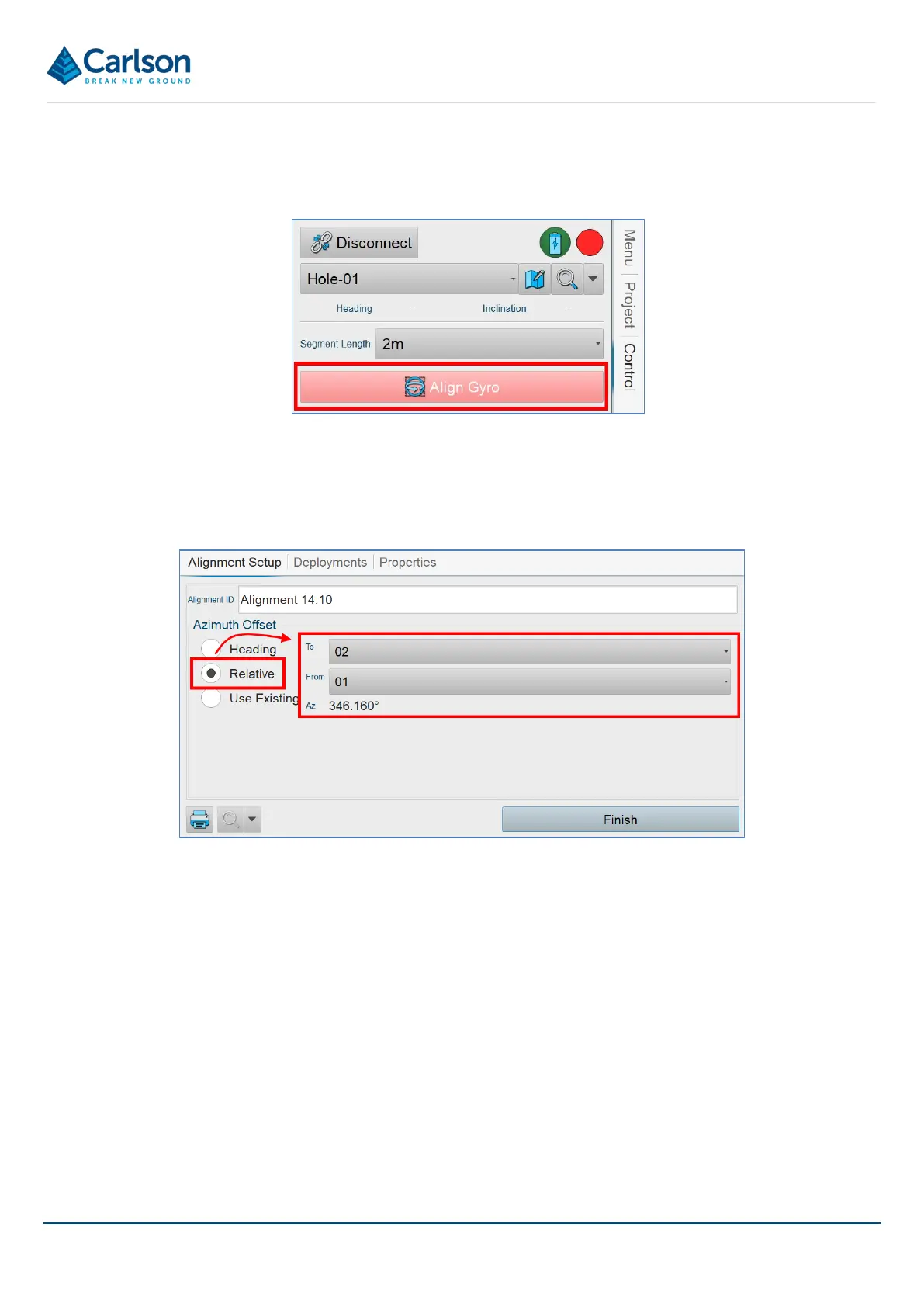
In the Control tab, tap Align Gyro.
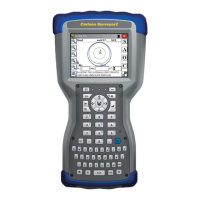
The Alignment Details window appears.
In the Azimuth frame, select Relative. From the drop-down lists, select From: 1 and To: 2. The heading from Hole
1 to Hole 2 is computed and used as the starting alignment heading for the survey.
Click Close to close the Alignment Details window.
5.3.1 Probes running version 1.0 firmware
The first generation of Boretrak2 probes run firmware version 1.0. These probes must be positioned with the
Boretrak logo pointing upwards when they are being aligned, see Figure 12. The software identifies when a probe
running version 1.0 firmware is connected. When you initiate an alignment, a message appears prompting you to
position the probe in this way.
Subsequent versions of firmware do not require the probe to be rolled in any specific way.
5.4 Deployment
In the Control tab, the Gyro button turns green once the heading has been initialised and then disappears.
If the Boretrak2 probe is moving, the alignment may be delayed. In this case, the gyro button turns yellow. The
Figure 13 Align Gyro button
Figure 14 Establishing a relative heading between two holes