BT2 user manual - H-5911-9004-02-B Page | 22
alignment will complete when the probe is stable.
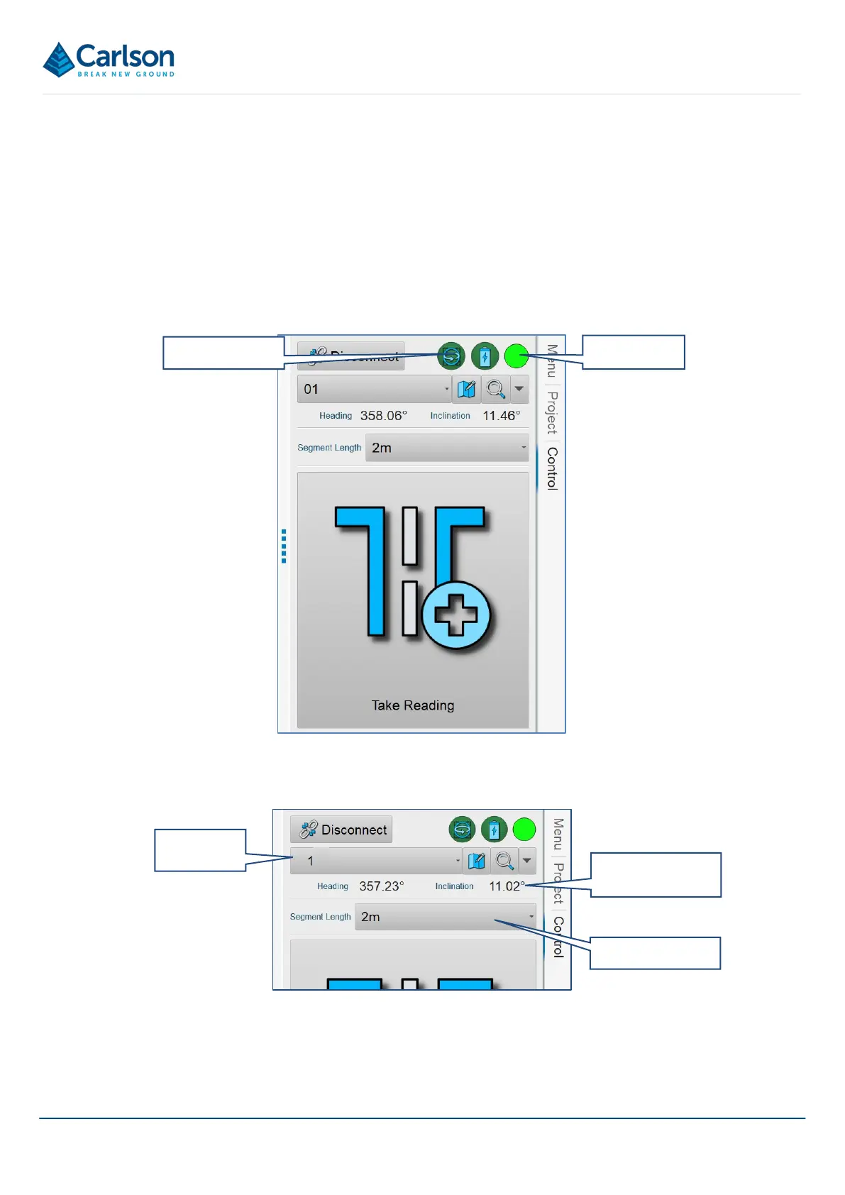
After a successful alignment, an Alignment icon appears in the top left hand of the Control tab which can be
accessed between holes to realign the gyro (see section 15.4).
From this point onwards, the IMU tracks the orientation of the probe in relation to this starting heading. The probe
logs all IMU data.
While the gyro is aligned, always handle the probe carefully and avoid knocking or sharply twisting the probe.
The icon in the top right of the Control tab flashes green, indicating that the probe LEDs are also flashing green.
This indicates that the gyro is aligned, and the survey can commence.
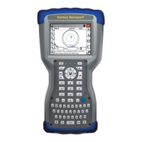
Check that Hole 1 is selected from the Hole drop down list. Select the correct Segment Length: usually 2 m.
The live Heading and Inclination values are displayed.
The Take Reading button is active and the deployment is ready to start.
Figure 16 Hole and Segment length selected
Alignment icon
LED icon
Figure 15 The Control tab after an alignment, ready to survey
Live heading and
inclination