19
Start-Up and Suction Pressure Transients
Operating a screw compressor without refrigerant flow
through the compressor can be harmful. When this
occurs, the evaporator typically will go into a vacuum,
leading to very high pressure ratios and little mass flow to
carry the heat away from the screw rotors. This situation
most often occurs during start-up when the refrigerant
may be in another part of
the system. This is tolerable for
short periods of time. The Paragon screw compressor
should not be allowed to operate with a suction pressure
less than 0 psig (vacuum) for more than 1 minute after a
“cold” start. (Contact Carlyle Application Engineering for
more information on cold starts.)
If a compressor is allowed to operate for longer periods of
time without refrigerant flow, catastrophic damage may
occur to the screw rotors, rotor housing, and disc
harge
housing, requiring compressor replacement.
Oil Supply at Compressor
To reduce the possibility of liquid refrigerant becoming
entrained in the oil during an OFF cycle, it is recom-
mended that the temperature of the oil entering the com-
pressor is kept above the outdoor ambient as shown in
Fig. 13. See Section 4.0 for additional information.
Allowable Temperature Ranges
See Table 7 for allowable temperature ranges.
Table 7 — Allowable Temperature Ranges
Unloader System Control Points
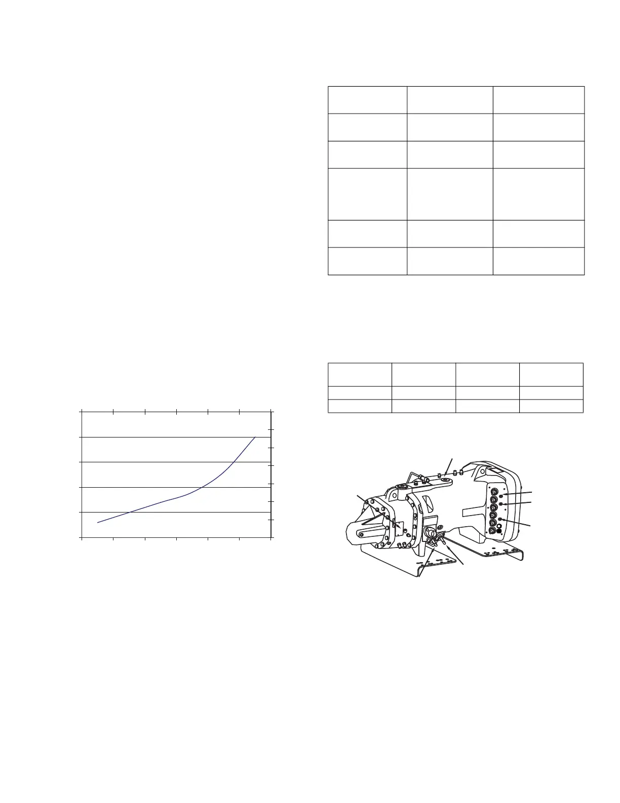
Table 8 shows the proper control states for the slide valve
solenoids. See Fig. 14 for solenoid locations.
Table 8 — Solenoid Control States
* Maintain capacity: Solenoid activation after proper slide valve position
has been attained.
The compressor will start with minimum power draw in
the fully unloaded state. There is no minimum
or maxi-
mum time limit immediately after start-up for which the
compressor must operate in the unloaded state.
However, it is recommended that the compressor oper-
ates unloaded for a minimum load for 30 seconds just
prior to shut down. This will ensure the compressor is
fully unloaded on the subsequent start, and means that
the compressor is drawing the minimum current when the
contactors open to
shut down the compressor.
Outdoor Ambient Temperature [OAT] (ºF)
Min Delta Oil Temp
>
Ambient (ºF)
0
2
4
6
8
10
12
14
-18 -7 4 16 27 38
Outdoor Ambient Temperature [OAT] (ºC)
Min Delta Oil Temp
>
Ambient (ºC)
Fig. 13 — Oil Temperature
CONTROL
POINT
MINIMUM MAXIMUM
Discharge
Gas
20°F (11°C)
superheat
210°F (99°C)
Economizer
Gas
Saturated
Liquid
9°F (5°C)
superheat
Suction
Gas
Saturated
Vapor
Can float if motor
and discharge
maximum temps
are met
Oil Supply at
Compressor
Refer to Fig. 13 140°F (60°C)
Motor
Windings
No limit 275°F (135°C)
INCREASE
CAPACITY
DECREASE
CAPACITY
PARTIAL*
SOLENOID #1 Energized De-Energized De-Energized
SOLENOID #2 Energized De-Energized Energized
Fig. 14 — Solenoid Locations
SOLENOID 1
SOLENOID 2
HIGH PRESSURE
SWITCH
MOTOR
TEMPERATURE
SENSOR 2
COMMON
MOTOR
TEMPERATURE
SENSOR 1
SUCTION
TEMPERATURE
 Loading...


