14 Specifications subject to change without notice. 38MGR-04SM
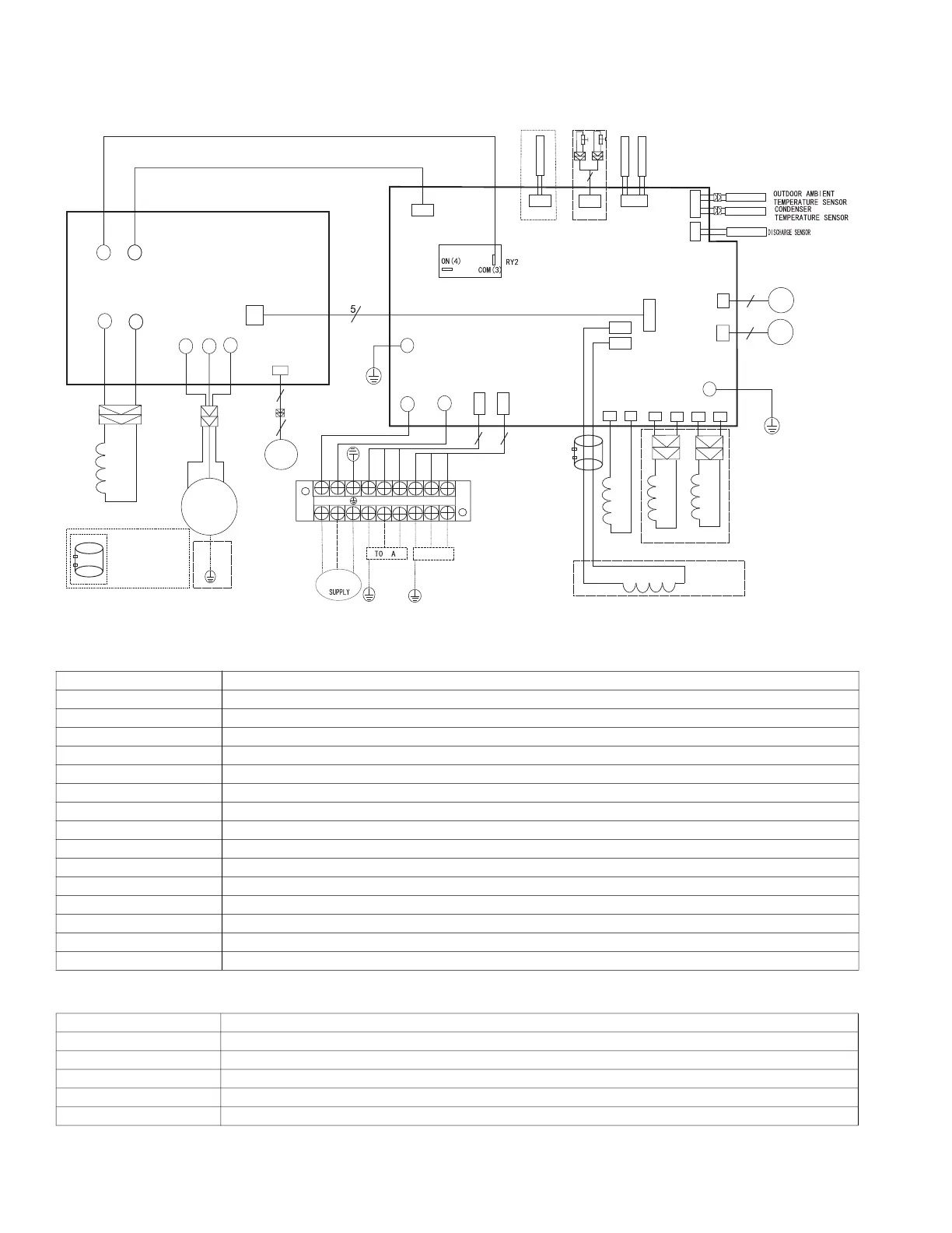
WIRING DIAGRAMS
Size 18K
Fig. 14 — Size 18K - 2 Zone
Table 6 — Size 18K - 2 Zone Max Codes
Table 7 — Outdoor Unit IPM Board
CODE PART NAME
CN3~CN4 Input: 230VAC High voltage
CN23,CN25 Output: Pin1 (Connection of the high voltage)---“S”Pin2~Pin3 (230VAC High voltage)---“L1 & L2”
P1~P2 Output: Connection of the REACTOR
CN1~CN2 Output: 230VAC High voltage ----4 Way Valve
CN5~CN6 Output: 230VAC High voltage----Compressor Crankcase Heater
CN8~CN9 Output: 230VAC High voltage----Chassis Crankcase Heater
P-1~P-2 Connection to the earth
CN18, CN19 Output: Pin1-Pin4: Pulse waveform (0-12VDC), Pin5, Pin6 (12VDC)--EEV
CN7 Input:Pin1 (0-5VDC), Pin2 (5VDC)--Discharge Sensor
CN17 Input: Pin3, Pin4 (5VDC), Pin2 (0VDC), Pin1, Pin5 (0-5VDC)-Cond. and Ambient Temperature
CN15 Input: Pin1, Pin3, Pin5 (5VDC) Pin2, Pin4, Pin6 (0-5VDC)--IDU Pipe Temp
CN14 Input: Pin2, Pin4 (0VDC), Pin1, Pin3 (0-5VDC)---H/L Pressure Switches
CN12 Input: Pin1 (0-5VDC), Pin2 (5VDC)--Compressor Temp
CN29~L-OUT Output: 230VAC High voltage--to IPM Board
CN 21 Connect to IPM BOARD
CODE PART NAME
CN4~CN5 Input: 230VAC High voltage---from the Main Board
CN2~CN3 Output: Connection of the REACTOR
U~V~W Connection to compressor voltage among phases 0~200VAC
CN14 Connection to DC FAN
CN1 Connection to MAIN BOARD
COMPRESSOR
CN1
U(R)
V(S)
W(C)
ELECTRONIC
EXPANSIVE
VALVE
BLUE
BLACK
U
V
W
CN7
VALVE-A
INDOOR PIPE
OUT TEMP
MAIN BOARD
CN19
CN17
T4
T3
P-1
RED
CN18
VALVE-B
CN29
CN21
CN15
T2B
A
B
CN14
LOW/HIGH
CN12
CompTop
YELLOW
RED
LOW PRESSURE PROTECT
HIGH PRESSURE PROTECT
CN4
CN5
~
~
RED(BROWN)
BLUE
Y/G
L-OUT
Y/G
CN6
CN5
HEATER1
HEAT1
CN1
CN2
4-WAY
4-WAY
HEATER2
OPTIONAL
CN9
CN8
HEAT2
CN2
CN3
REACTOR
BLUE
BLUE
P2
P1
REACT0R2 R05094A
OPTIONAL
WHITE
WHITE
Y/G
NOTE:Use the magnetic ring
(not supplied, optional part)
to hitch the connective cable
of indoor and outdoor units
after installation. one magnetic
ring is used for one cable.
DC FAN
6
CN14
L1-IN
L2-IN
CN25
CN23
S-A
S-B
CN3
CN4
BLACK
BLUE
BROWN
BLACK
RED
BROWN
BLUE
BLACK
Y/G
3
ELECTRONIC
EXPANSIVE
VALVE
3
6
P-2
POWER
L1(A)
TO B
S(A)
L2
L2(A)
L1
Y/G
Y/G
L1(B)
L2(B)
S(B)
3
3
 Loading...