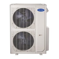
Do you have a question about the Carrier 38MGR Series and is the answer not in the manual?
Warnings for electrical shock, explosion, and equipment damage hazards.
Details unit sizes, kBTUh, voltage, and model numbers.
Comprehensive table of system specs including operating range, piping, refrigerant, electrical, and compressor data.
Tables and diagrams for unit dimensions and installation clearance requirements.
Electrical specs, wiring methods, and precautions for installation.
Wiring diagrams for various unit sizes and zone configurations.
Illustrates the automatic wiring and piping correction process.
Detailed wiring diagram and code list for the 18K unit.
Detailed wiring diagram and code list for the 24K unit.
Detailed wiring diagram and code list for the 30K unit.
Detailed wiring diagram and code list for the 36K unit.
Detailed wiring diagram and code list for the 48K unit.
Diagrams illustrating the refrigeration cycle for different unit sizes.
Guidelines for sizing refrigerant lines, long line apps, and system evacuation/charging.
Procedures for system evacuation using vacuum pumps and methods.
Details unit protections, compressor limits, and valve controls.
Describes cooling/heating mode operations, protections, and adjustments.
Conditions and actions for defrosting mode.
Lists tools and general steps for diagnosing and repairing units.
Explanation of outdoor PCB digital display codes and error messages.
Explanation of outdoor PCB digital display functions and error messages.
Functionality of the check switch (SW1) on the outdoor PCB.
Comprehensive table of outdoor PCB display codes and their meanings.
Troubleshooting flowchart for indoor fan speed control issues.
Diagnosis and solution for indoor unit mode conflicts.
Troubleshooting for EEPROM parameter errors.
Troubleshooting for communication issues between units.
Images and instructions for testing IPM boards and voltages.
Troubleshooting for zero crossing detection errors.
Troubleshooting for communication errors between IPM and main boards.
Troubleshooting sensor open/short circuit errors.
Troubleshooting voltage protection errors.
Troubleshooting PFC module protection errors.
Troubleshooting outdoor fan speed control issues.
Troubleshooting compressor top temperature protection errors.
Troubleshooting high pressure protection errors.
Troubleshooting low pressure protection errors.
Troubleshooting compressor current protection errors.
Troubleshooting compressor discharge temperature protection errors.
Troubleshooting condenser high temperature protection errors.
Troubleshooting IPM module protection errors.
Troubleshooting non-operation and sensor checks.
Table mapping Celsius/Fahrenheit to resistance values for sensors.
Procedures for checking compressor resistance and fan motor voltage.
Procedures for testing IPM continuity, 4-way valve, and EXV coil resistance.
Step-by-step instructions for disassembling size 18 units.
Step-by-step instructions for disassembling size 24 units.
Step-by-step instructions for disassembling size 30 units.
Step-by-step instructions for disassembling size 36 and 48 units.
| Refrigerant | R-410A |
|---|---|
| Voltage | 208/230V |
| Dimensions (Outdoor Unit) | Varies by model |
| Weight (Outdoor Unit) | Varies by model |
| Type | Air Conditioner |


 Loading...