16 Specifications subject to change without notice. 38MGR-04SM
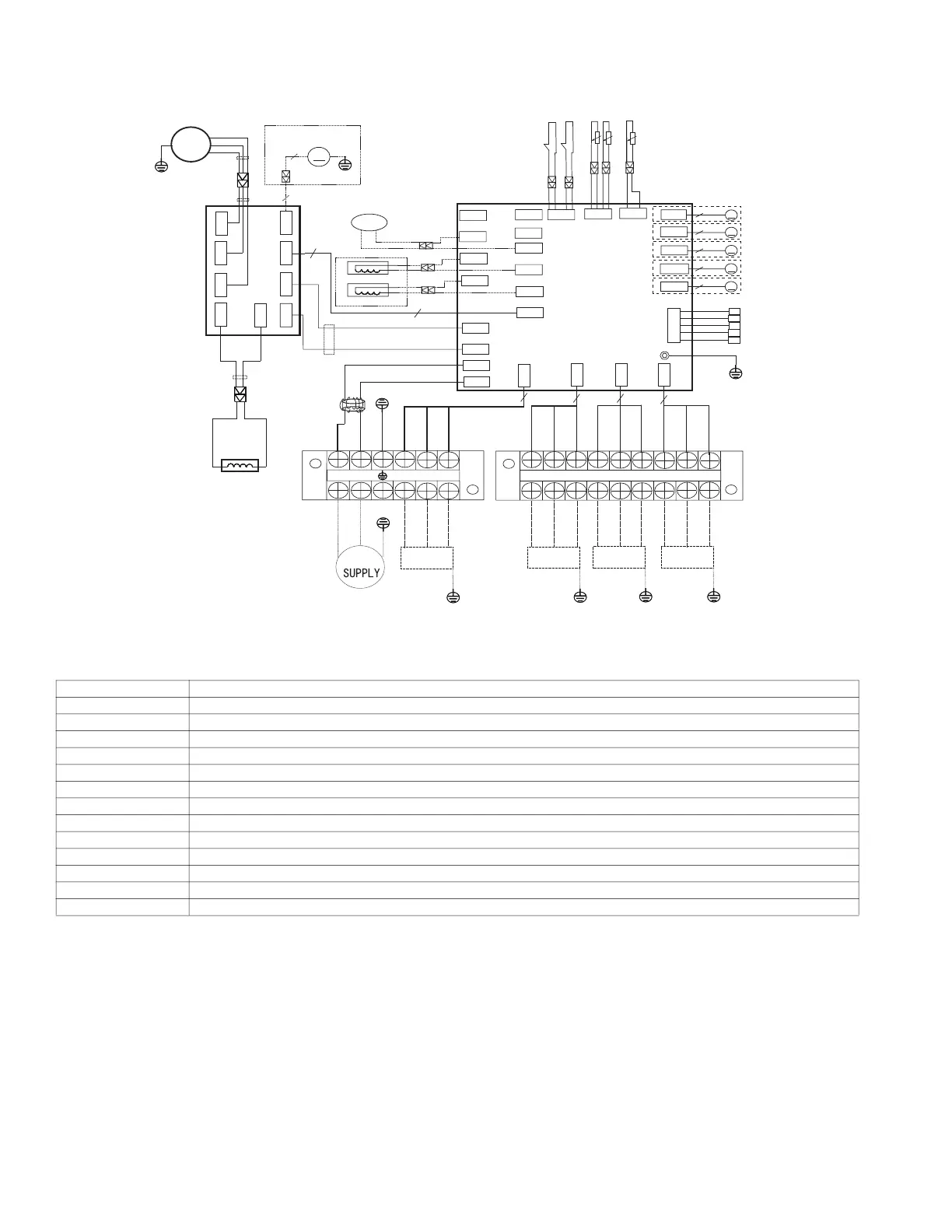
WIRING DIAGRAMS (CONT)
Size 30K
Fig. 16 — Size 30K - 4 Zone Max
Table 10 — Size 30K 4 Zone Max Codes
CODE PART NAME
CN1~CN2 Input: 230VAC High voltage
CN5~CN6 Output: 230VAC High voltage
P-1 Connection to the earth
CN10~CN44 Output: 230VAC High voltage Chassis Crankcase Heater
CN4~CN40 Output: 230VAC High voltage Compressor Crankcase Heater
CN3~CN22 Output:230VAC High voltage
CN17~CN21 Output: Pin1-Pin4: Pulse waveform (0-12VDC), Pin5, Pin6 (12VDC)
CN7 Output: Pin1 (12VDC), Pin2 (5VDC), Pin3 (EARTH)
CN27~CN30 Output: Pin 2~Pin 3 (230VAC High voltage) - IDU Power & “S”
CN13 Pin1, Pin3, Pin5, Pin7, Pin9 (5VDC); Pin2, Pin4, Pin6, Pin8, Pin10 (0-5VDC)
CN33 Input: Pin1 (0-5VDC), Pin2 (5VDC) - Discharge Temp
CN8 Input: Pin3, Pin4 (5VDC), Pin2 (0VDC), Pin1, Pin5 (0-5VDC) T3 & T4
CN9 Input: Pin2, Pin4 (0VDC), Pin1, Pin3 (0-5VDC) H/L Pressure Switches
COMP
FM1
MAIN BOARD
U
V
W
L
DRIVER BOARD
7
7
YELLOW
Applicable to the units
adopting DC motor only
CN52
CN6
SV
4-WAY1
BLUE
HEAT_D
HEAT_Y
OPTIONAL
3
BLACK
RED
BLUE
BLUE
YELLOW
BLACK
CN20
M
5(6)
A
CN21
M
5(6)
B
CN17
M
5(6)
C
CN18
M
5(6)
D
CN19
M
5(6)
E
T2B-A B C D E
CN13
INDOOR PIPE OUT
TEMP A B C D E
CN5
CN2
CN1
CN30
CN29
CN27
CN28
P-1
Y/G
BLACK
BLUE
BROWN
POWER
S(D)
L2(D)
L1(D)
S(C)
L1(C)
L2(C)
L1(B)
L2(B)
S(B)
L1 L2
L1(A)
L2(A)
S(A)
TO A
Y/G
TO B
Y/G
TO C
Y/G
TO D
Y/G
BLACK
BLUE
BROWN
BLACK
BLUE
BROWN
BLACK
BLUE
BROWN
BLACK
RED
YELLOW
L-PRO
T3
T4
H-PRO
TP
CN33
CN8
CN9
CN41
CN42
CN43
CN3
CN22
CN4
CN10
CN7
CN44
CN40
BLUE
BLUE
BLUE
RED
BLACK
BLACK
RED
CN51
CN53
CN54
RED
CN55
CN19
3
Y/G
Y/G
U
V
W
BLUE
3
3
3
3
 Loading...