EasyManuals Logo

Carrier 38MGR Series User Manual

Carrier 38MGR Series
102 pages
To Next Page IconTo Next Page
To Previous Page IconTo Previous Page
Page #51 background imageLoading...
Page #51 background image
38MGR-04SM Specifications subject to change without notice. 51
DIAGNOSIS AND SOLUTION (CONT)
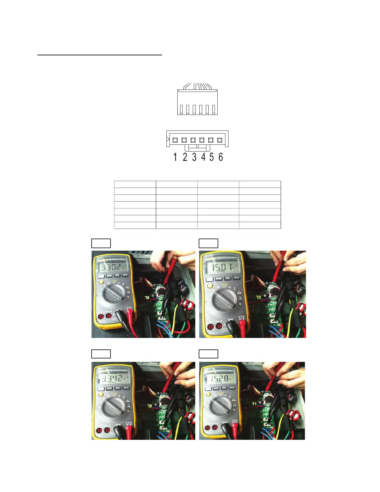
Index 1:
DC fan motor (control chip is inside fan motor)
Power on and when the unit is in standby, measure the voltage of pin1-pin3, pin4-pin3 in fan motor connector. If the value of the voltage is not
in the range showing in the table below, the PCB needs to be replaced.
Fig. 60 — DC Fan Motor
Fig. 61 —Test the Voltage
NO. COLOR SIGNAL VOLTAGE
1 Red Vs/Vm 200~380V
2 --- --- ---
3 Black GND 0V
4 White Vcc 13.5~16.5V
5 Yellow Vsp 0~6.5V
6 Blue FG 13.5~16.5V
Vs
Vcc
Vsp FG

Table of Contents

Questions and Answers:

Question and Answer IconNeed help?

Do you have a question about the Carrier 38MGR Series and is the answer not in the manual?

Carrier 38MGR Series Specifications

General IconGeneral
BrandCarrier
Model38MGR Series
CategoryAir Conditioner
LanguageEnglish

Related product manuals