38MGR-04SM Specifications subject to change without notice. 17
WIRING DIAGRAMS (CONT)
Size 30K
Table 11 — 30K - 4 Zone Max
Table 12 — 30K - 4 Zone Max
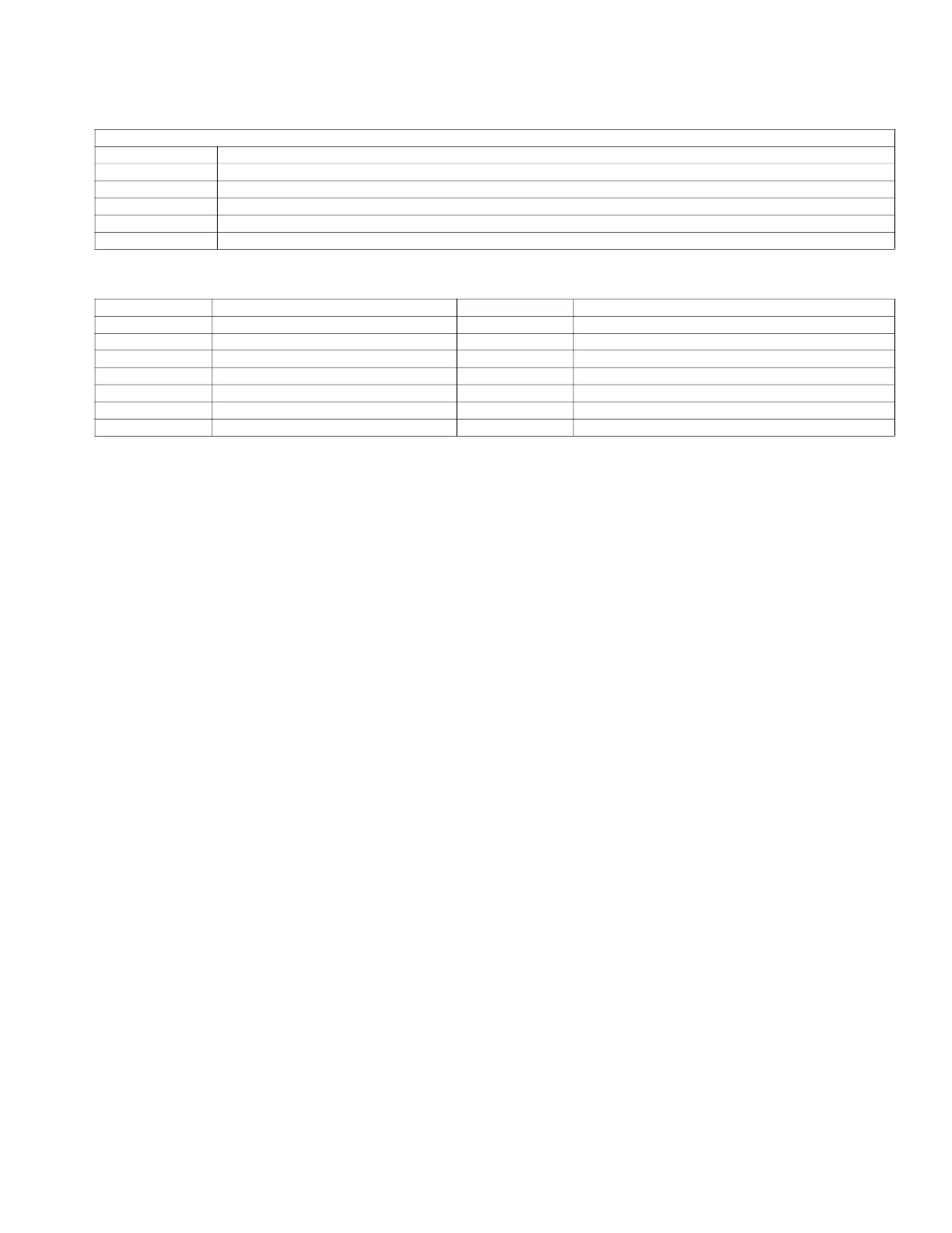
OUTDOOR UNIT PFC & IPM BOARD
CODE PART NAME
CN53~CN54 Input: 230VAC High voltage
CN55 Output: Pin1 (12VDC),Pin2 (5VDC),Pin3 (EARTH)
CN19 Pin1~Pin3: Connect to FAN voltage among phases 0~200VAC
U~V~W Connect to compressor voltage among phases 0~200VAC
CN51~CN52 CN51~EARTH,CN52~EARTH Output: 224-380VDC High voltage
CODE PART NAME CODE PART NAME
COMP COMPRESSOR L PFC INDUCTOR
CAP1 FAN MOTOR CAPACITOR L-PRO LOW PRESSURE SWITCH
HEAT CRANKCASE HEATING TP EXHAUST TEMPERATURE SENSOR
FM1 OUTDOOR DC FAN SV 4-WAY VALVE
FAN1 OUTDOOR AC FAN T3 CONDENSER TEMPERATURE SENSOR
EEV ELECTRONIC EXPANSION VALVE T4 OUTDOOR AMBIENT TEMPERATURE SENSOR
H-PRO HIGH PRESSURE SWITCH TH HEATSINK TEMPERATURE SENSOR
 Loading...