S-A,S-B,S-C,S-D,S-E
(3p/3p/3p/3p/3p,white)
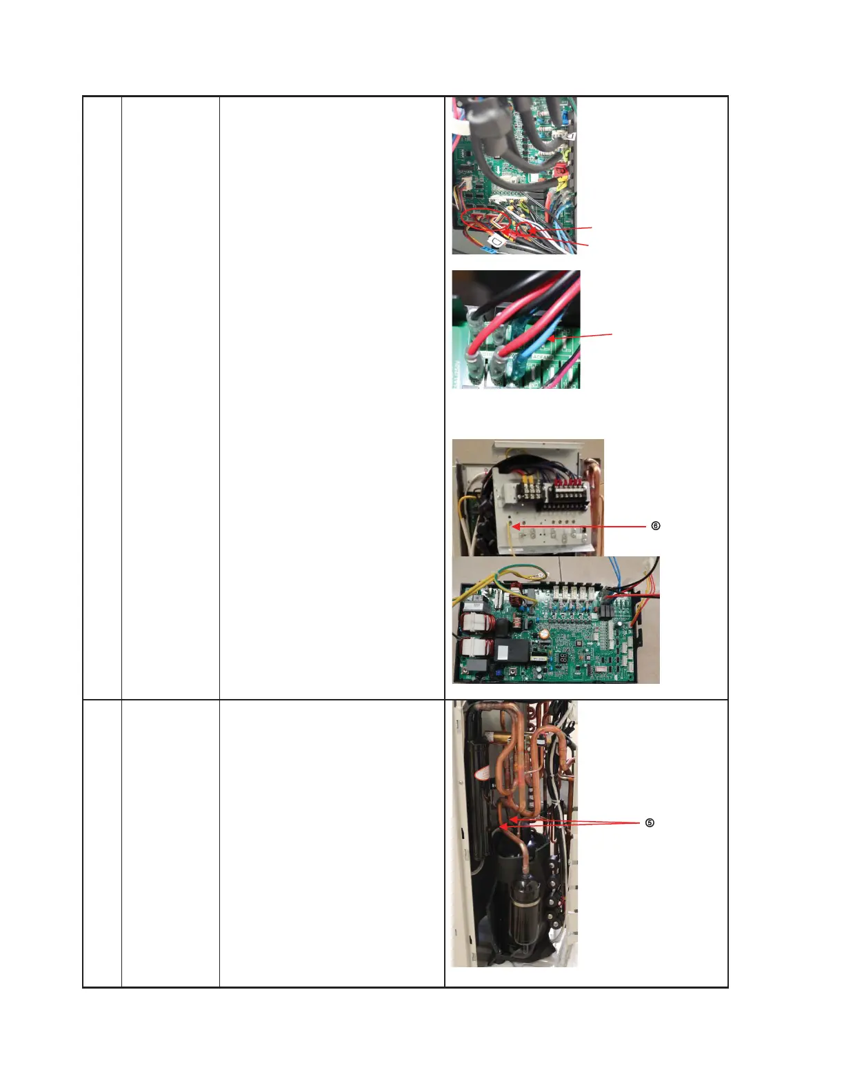
CN10: High and low pressure switch
(2p/2p, white)
Wires:
CN17/CN18: 4-way valve (blue-blue)
CN19/CN20: connected to crankcase
heating cable. (black-red)
CN24/CN25: Electric heater of
chassis (orange-orange)
CN1:L-IN (red)
CN3:N-IN (black)
6)
Disconnect the grounding
wire (yellow-green) after
removing the big handle.
7)
Remove the PCB board.
4 Compressor How to remove the compressor
1) Complete steps 5 and 6 in
the Fan Assembly section
and all the steps in the
Panel Plate section.
2) Extract the refrigerant gas.
3) Remove the sound insulation
material and the crankcase
heating cable.
4) Remove the compressor
terminal cover, disconnect
the crankcase electric heater
wires and compressor from
the terminal.
CN17/CN18
CN19/CN20
CN24/CN25
CN30/CN23
CN10
 Loading...