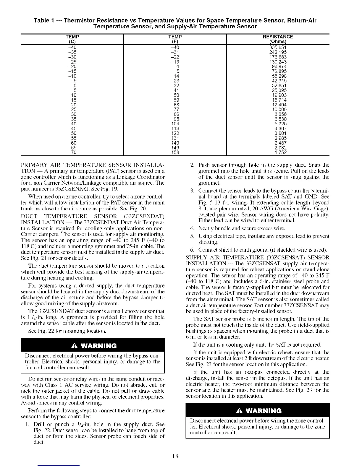
Table 1 -- Thermistor Resistance vs Temperature Values for Space Temperature Sensor, Return-Air
Temperature Sensor, and Supply-Air Temperature Sensor
TEMP
(c)
-40
-35
-30
-25
-20
-15
-10
-5
0
5
10
15
20
25
30
35
40
45
50
55
60
65
70
TEMP
(F)
-40
-31
-22
-18
-4
5
14
28
32
4!
50
59
66
77
86
95
104
118
122
13!
140
149
!58
RESISTANCE
(Ohms)
335,651
242,195
176,683
130,243
96,974
72,895
55,298
42,315
32,651
25,395
19,903
15,7!4
12,494
10,000
8,056
6,530
5,325
4,367
3,601
2,985
2,487
2,082
1,752
PRIMARY AIR TEMPERATURE SENSOR INSTALLA-
TION -- A primary air temperature (PAT) sensor is used on a
zone controller which is functioning as a Linkage Coordinator
for a non Carrier Network/Linkage compatible air source. The
p_ut number is 33ZCSENPAT. See Fig. 19.
When used on a zone controller, try to select a zone control-
ler which will _fllow installation of the PAT sensor in the main
trunk, as close to the air source as possible. See Fig. 20.
DUCT TEMPERATURE SENSOR (33ZCSENDAT)
INSTALLATION -- The 33ZCSENDAT Duct Air Tempera-
ture Sensor is required for cooling only applications on non-
Canier &_mpers. The sensor is used for supply air monitoring.
The sensor has tin operating range of -40 to 245 F (=40 to
118 C) and includes a mounting grommet and 75-in. cable. The
duct temperature sensor must be installed in the supply air duct.
See Fig. 21 for sensor dettdls.
The duct temperature sensor should be moved to a location
which will provide the best sensing of the supply-air tempera-
ture during heating and cooling.
For systems using a ducted supply, the duct temperature
sensor should be located in the supply duct downstream of the
dischalge of the air source and before the bypass &_mper to
allow good mixing of the supply airstream.
The 33ZCSENDAT duct sensor is a small epoxy sensor that
is l l/4-in, long. A grommet is provided for filling the hole
around the sensor cable after the sensor is located in the duct.
See Fig. 22 for mounting location.
Disconnect electric_fl power before wiring the bypass con-
trollel: Electrical shock, personal injury, or &tmage to the
fan coil controller can result.
Do not run sensor or relay wires in the same conduit or race-
way with Class 1 AC service wiring. Do not abrade, cut, or
nick the outer jacket of the cable. Do not pull or &'aw cable
with a force that may harm the physical or electrical properties.
Avoid splices in any control wiring.
Perform the following steps to connect the duct temperature
sensor to the bypass controller:
1. Drill or punch a l/4-in, hole in the supply duct. See
Fig. 22. Duct sensor can be installed to hang from top of
duct or from the sides. Sensor probe can touch side of
duct.
2. Push sensor through hole in the supply duct. Snap the
grommet into the hole until it is secure. Pull on the leads
of the duct sensor until the sensor is snug ag_dnst the
grommet.
3. Connect the sensor leads to the bypass controller's termi-
md bo;ud at the terminals labeled SAT grad GND. See
Fig. 5-13 for wiring. If extending cable length beyond
8 fl, use plenum rated, 20 AWG (American Wire Gage),
twisted pair wire. Sensor wiring does not have pokuity.
Either lead can be wired to either terminal.
4. Neatly bundle and secure excess wire.
5. Using electric_d tape, insulate any exposed lead to prevent
shorting.
6. Connect shield to emlh ground (if shielded wire is used).
SUPPLY AIR _EMPERATURE (33ZCSENSAT) SENSOR
INSTALLATION- The 33ZCSENSAT supply air tempera-
ture sensor is required for reheat applications or stand-alone
operation. The sensor has an operating range of -40 to 245 F
(-40 to 118 C) and includes a 6-in. stainless steel probe and
cable. The sensor is factory-supplied but must be relocated for
ducted heat. The SAT must be installed in the duct downstream
from the air termimd. The SAT sensor is _dso sometimes called
a duct air temperature sensol: Part number 33ZCSENSAT may
be used in place of the factory-installed sensol:
The SAT sensor probe is 6 inches in length. The tip of the
probe must not touch the inside of the duct. Use field-supplied
bushings as spacel.s when mounting the probe in a duct that is
6 in. or less in diametel:
If the unit is a cooling only unit, the SAT is not required.
If the unit is equipped with electric reheat, ensure that the
sensor is installed at least 2 ft downstream of the electric heatel:
See Fig. 23 for the sensor location in this application.
If the unit has tin octopus connected directly at the
discharge, install die sensor in the octopus. If the unit has an
electric heater, the two-foot minimum distance between the
sensor and the heater must be maintained. See Fig. 23 for the
sensor location in this application.
Disconnect electrical power before wiring the zone control-
ler Electrical shock, personal injury, or &image to the zone
controller can result.
18
 Loading...


