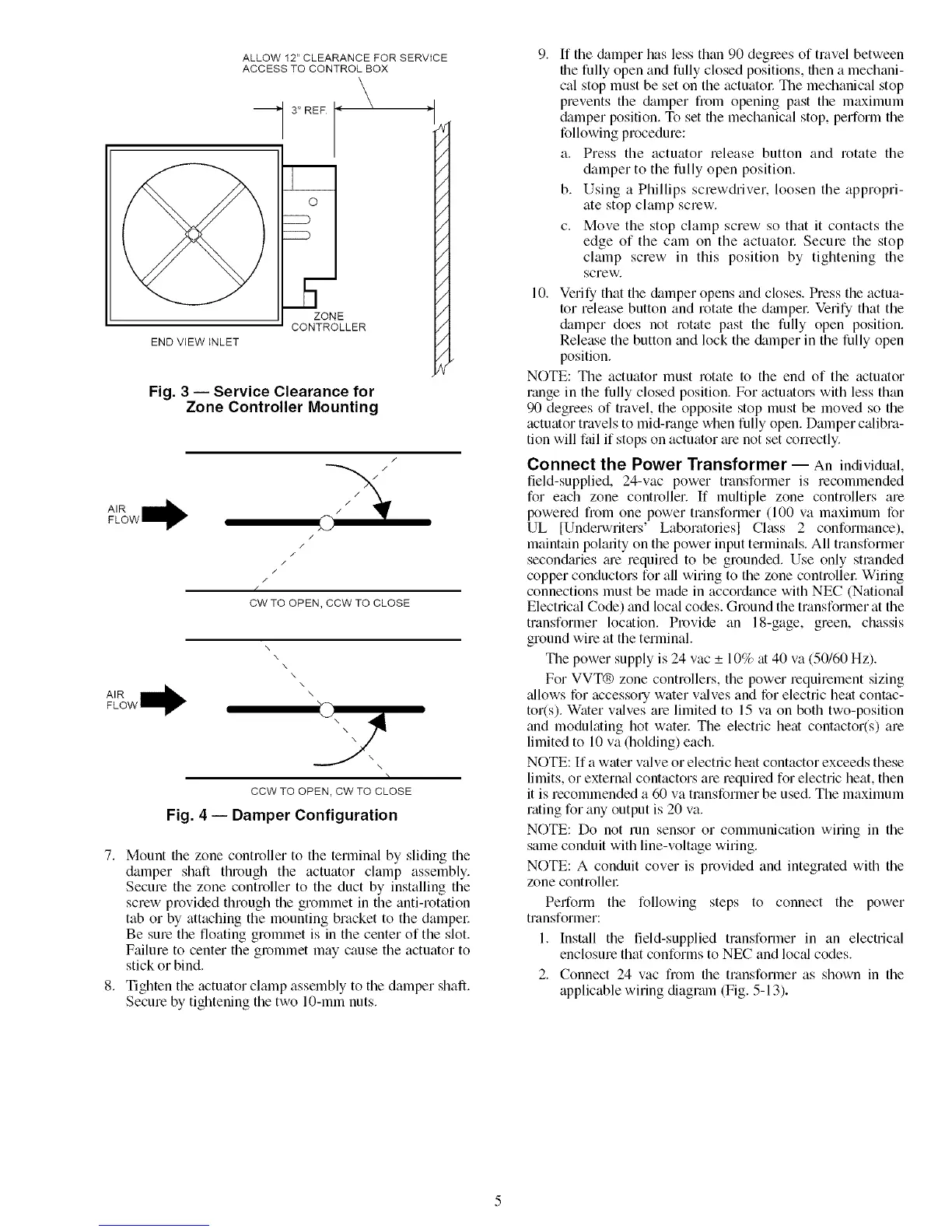
END VIEW INLET
-- 3" REF
ZONE
CONTROLLER
ALLOW 12" CLEARANCE FOR SERVICE
ACCESS TO CONTROL BOX
_lar
/
/
/
/
/
/
/
/
/
/
/
/
/
/
/
/
N
Fig. 3 -- Service Clearance for
Zone Controller Mounting
//
/
/
/
//
K /
CW TO OPEN, CCW TO CLOSE
x
\
x
\
\
\
CCW TO OPEN, CW TO CLOSE
Fig. 4 -- Damper Configuration
7. Mount the zone controller to the terminal by sliding the
damper shaft through the actuator clamp assembly.
Secure the zone controller to the duct by installing the
screw provided through the grommet in the anti-rotation
tab or by attaching the mounting bracket to the dampec
Be sure the floating grommet is in the center of the slot.
Failure to center the grommet may cause the actuator to
stick or bind.
8. Tighten the actuator clamp assembly to the damper shaft.
Secure by tightening the two 10-mm nuts.
9. ff the &_mper has less than 90 degrees of travel between
the fully open and fully closed positions, then a mechani-
cal stop must be set on the actuatol: The mechanical stop
prevents the &_mper from opening past the maximum
damper position. To set the mechanical stop, perform the
following procedure:
a. Press the actuator release button and rotate the
damper to the fully open position.
b. Using a Phillips screwdriver, loosen the appropri-
ate stop clamp screw.
c. Move the stop clamp screw so that it contacts the
edge of the cam on the actuatol: Secure the stop
clamp screw in this position by tightening the
screw.
10. Verify that the &Lmper opens and closes. Press the actua-
tor release button and rotate the dmnpel: Verify that the
damper does not rotate past the fully open position.
Release the button and lock the &_mper in the fully open
position.
NOTE: The actuator must rotate to the end of the actuator
range in the fully closed position. For actuators with less than
90 degrees of travel, the opposite stop must be moved so the
actuator travels to mid-range when fully open. Damper calibra-
tion will f_dl if stops on actuator _ue not set correctly.
Connect the Power Transformer -- An individual,
field-supplied, 24-vac power transformer is recommended
for each zone controller. If multiple zone controllers are
powered fiom one power transformer (100 va maximum for
UL [Underwriters' Laboratoriesl Class 2 conformance),
maintain polarity on the power input terminals. All transformer
second;uies ;ue required to be grounded. Use only stranded
copper conductors for all wiring to the zone controllec Wiring
connections must be made in accordance with NEC (National
Electrical Code) and local codes. Ground the transformer at the
transformer location. Provide an 18-gage, green, chassis
ground wire at the terminal.
The power supply is 24 vac _+10% at 40 va (50/60 Hz).
For VVT® zone controllers, the power requirement sizing
_dlows for accessory water v_dves and for electric heat contac-
tot(s). Water v_dves are limited to 15 va on both two-position
and modulating hot watel: The electric heat contactor(s) are
limited to 10 va (holding) each.
NOTE: If a water valve or electric heat contactor exceeds these
limits, or external contactors are required for electric heat, then
it is recommended a 60 va transformer be used. The maximum
rating for any output is 20 va.
NOTE: Do not run sensor or communication wiring in the
same conduit with line-voltage wiring.
NOTE: A conduit cover is provided and integrated with the
zone controllel:
Perform the following steps to connect the power
transformer:
1. Install the field-supplied transformer in an electrical
enclosure that conforms to NEC and loc_d codes.
2. Connect 24 vac from the transformer as shown in the
applicable wiring diagrmn (Fig. 5-13).
 Loading...


