NON-LINKAGE CONTROLLED AIR SOURCES --In sys-
tems with Non-Linkage central air sources or central air
sources that do not support Linkage, the zone coordination
ftmction of Linkage can still be provided by the Linkage func-
tion conttfined within a Linkage Coordinatoc In these cases, the
zone configured as the Linkage Coordinator will determine the
operational mode of the air source through its bypass controller
pressure sensol: Once the air source is determined to be opera-
tion_d, the Linkage Coordinator will attempt to determine the
air source mode (heating or cooling) by measuring the supply
air temperatme from the air source by either a primary air
temperature sensor or a bypass duct temperature sensoc A
field-supplied primary air temperature sensor is required.
The modes that can be deterlnined are Cooling, Heating,
Free Cooling, or Off. If a sensor is not installed, or the sensor
fails, then the Linkage Coordinator will default to the cooling
mode. The mode and air source status is then transmitted down
to the zones by the Linkage Coordinatoc
NOTE: If Linkage communication should fail between a
linked air source and its Linkage Coordinator for mole then
5 minutes, the Linkage Coordinator will generate a Linkage
Failure akum and will levert back a Non-Linkage air source
control. Once Linkage communication has been re-established
it will automatically begin controlling the _dr source.
System Modes -- The followingmodes are determined
by the Linkage Coordinator through the Linkage &_ta exchange
when there is a linked, controlled air source or by using its
bypass controller and prim;uy air sensor if the there is a
non-linkage controlled air source. Some modes will not be
av;filable if the there is a non-Linkage controlled air source. All
the listed modes tue available if there is a linked CmTier
communicating network controlled air source depending on the
avtfilable input options of the of the air source. Each mode
description identities if and how that mode is detemfined if
there is a non-linkage controlled air source.
OFF MODE -- The linked air source will determine this
mode based on its fan status input under normal operating
conditions. For a non-Linkage controlled air source, the
Linkage Coordinator will determine if the air source is opera-
tion_d (the fan is on) by determining if the bypass pressure can
be measured. If no pressure can be measured then the Linkage
Coordinator controller concludes that the air source is off and
all zone dampers will go to 70% open. If pressure is measured,
then the Linkage Coordinator concludes that the air source in
on. If no bypass controller is present then the system will be
considered to be always on.
HEAT MODE -- The linked air source is in heat mode due to
a request for from Linkage Coordinatoc For a non-Linkage
controlled air source, when the fan is determined to be on, the
Linkage Coordinator controller reads the prim_uy _fir tempera-
ture value. If the duct temperature is 5° F greater than the
reference zone temperature and the reference zone is greater
than 65 E or if the reference zone is less than 65 F and the duct
temperature is 10° F greater than the reference zone tempera-
ture, then the mode is determined to be heating.
COOL MODE -- The linked air source is in cool mode due to
a request for from Linkage Coordinator For a non-linkage
controlled air source, when the fan is determined to be on, the
Linkage Coordinator controller reads the primtuy air tempera-
ture v_flue. If the temperature is less than the reference zone
temperature, as calculated by the Linkage Coordinator control-
ler. minus 2° E the mode is determined to be cooling.
FREECOOL MODE- The following conditions must be
present in the linked air source for free cooling mode:
• the average zone temperature value is greater than the
average unoccupied zone cooling temperature set point
• the current time is between 3:00 AM and 7:00 AM
• the air source is providing cooling to the system
If the above conditions are true, then the mode is deter-
mined to be Free Cooling. This mode is then communicated to
_dl zone controllers associated (linked) with the Linkage
Coordinator controllec For a non-Linkage controlled air
source, this will be same as COOL mode if the criteria for
COOL mode is met as described above.
PRESSURIZATION MODE -- If the linked air source has
its optional Pressurization input closed, it will transmit this
mode to the Linkage Coordinator If this mode is active then all
zones will open the &_mpers to the cooling maximum dalnper
position, series fan boxes will have their fans forced on and
parallel fan boxes will have their fan forced off. This mode is
not available for if there is a non-Linkage controlled air source.
EVACUATION MODE -- If the linked air source has its op-
tional Fire Shutdown or Evacuation input closed, it will
transmit this mode to the Linkage Coordinatoc If this mode is
active then all zone dampers will be fully closed and series and
parallel fan boxes will have their fans forced off. This mode is
not available for if there is a non-Linkage controlled _firsource.
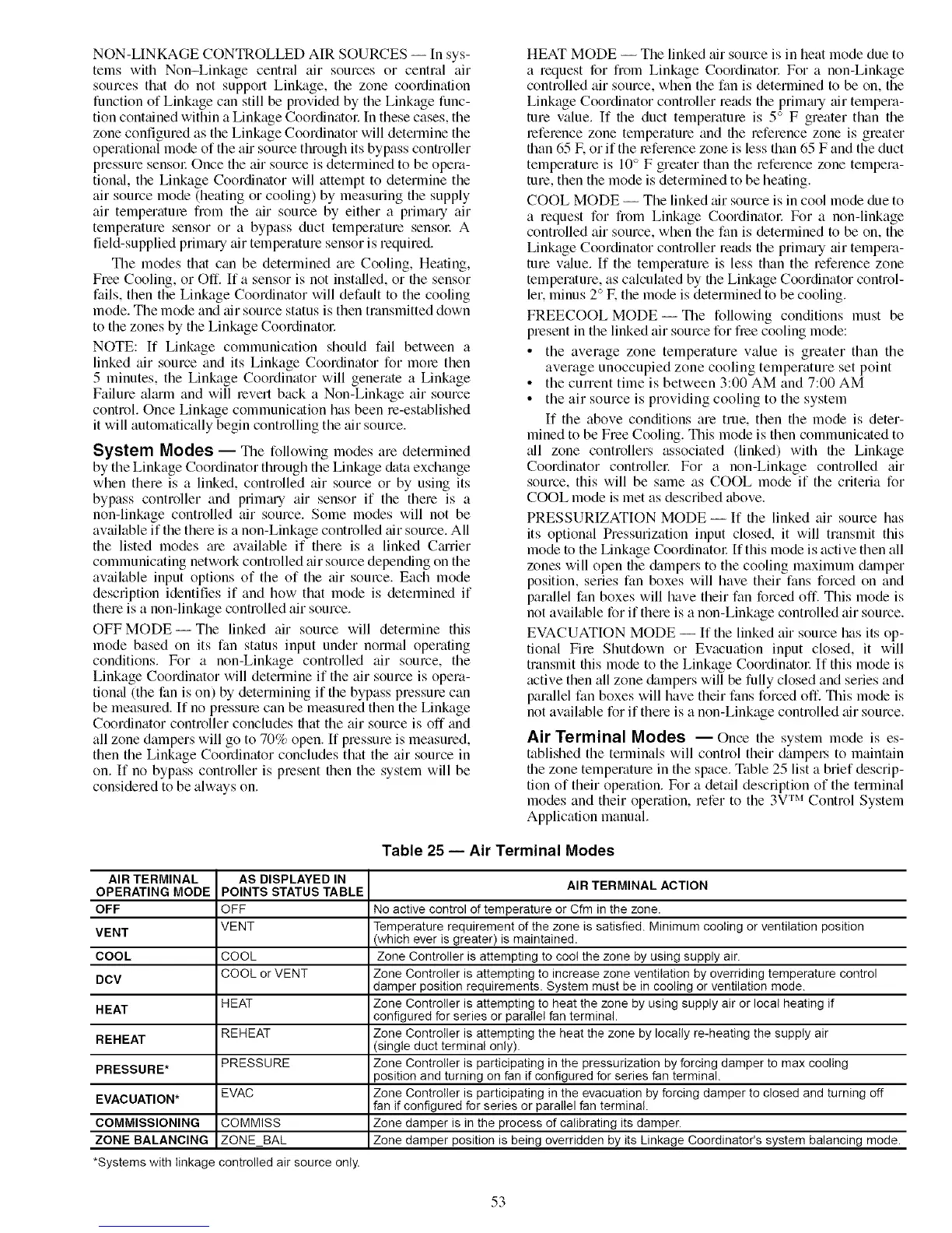
Air Terminal Modes --Once the system mode is es-
tablished the terminals will control their &tmpel_ to maintain
the zone temperature in the space. Table 25 list a brief descrip-
tion of their operation. For a det_fil description of the terlninal
modes and their operation, refer to the 3VTM Control System
Application manual.
Table 25 -- Air Terminal Modes
AIR TERMINAL
OPERATING MODE
OFF
VENT
COOL
DCV
HEAT
REHEAT
PRESSURE*
EVACUATION*
COMMISSIONING
ZONE BALANCING
AS DISPLAYED IN
POINTS STATUS TABLE
OFF
VENT
COOL
COOL or VENT
HEAT
REHEAT
PRESSURE
EVAC
COMMISS
ZONE_BAL
AIR TERMINAL ACTION
No active control of temperature or Cfm in the zone.
Temperature requirement of the zone is satisfied. Minimum cooling or ventilation position
(which ever is greater) is maintained.
Zone Controller is attempting to coot the zone by using supply air.
Zone Controller is attempting to increase zone ventilation by overriding temperature control
damper position requirements. System must be in cooling or ventilation mode.
Zone Controller is attempting to heat the zone by using supply air or local heating if
configured for series or parallel fan terminal.
Zone Controller is attempting the heat the zone by locally re-heating the supply air
(single duct terminal only).
Zone Controller is participating in the pressurization by forcing damper to max cooling
position and turning on fan if configured for series fan terminal.
Zone Controller is participating in the evacuation by forcing damper to closed and turning off
fan if configured for series or parallel fan terminal.
Zone damper is in the process of calibrating its damper.
Zone damper position is being overridden by its Linkage Coordinator's system balancing mode.
*Systems with linkage controlled air source only.
53
 Loading...


