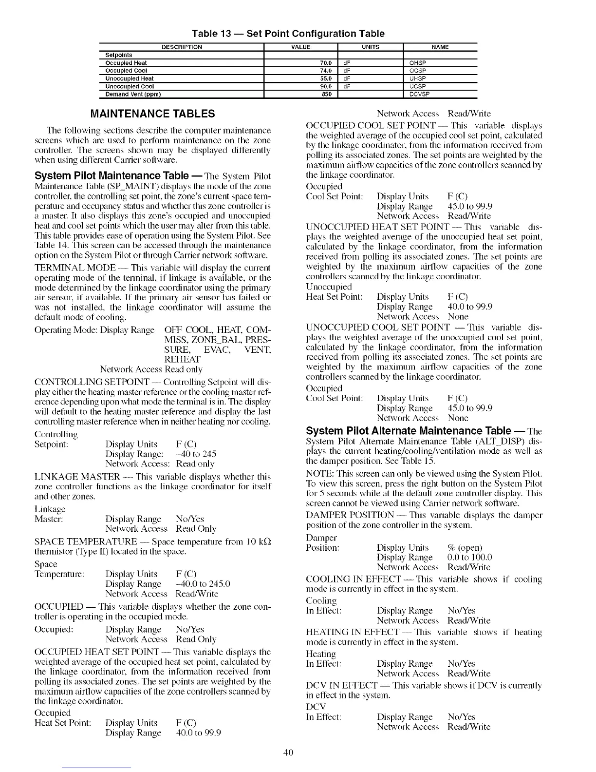
Table 13 -- Set Point Configuration Table
DESCRIPTION VALUE UNITS
Setpolnts
Occupied Heat 70.0 dF
Occupied Cool 74.0 dF
Unoccupied Heat 55.0 dF
Unoccupied Cool 90.0 dF
Demand Vent(ppm) 850
NAME
OHSP
OCSP
UHSP
UCSP
DCVSP
MAINTENANCE TABLES
The following sections desclibe the computer maintenance
screens which me used to perform maintenance on the zone
controllel: The screens shown may be displayed differently
when using different Carrier sollwme.
System Pilot Maintenance Table -- The SystemPilot
Maintenance Table (SP_MAINT) displays the mode of the zone
controllek file controlling set point, the zone's current space tem-
perature and occupancy status and whether this zone controller is
a mastel: It also displays this zone's occupied and unoccupied
heat and cool set points which the user may _dter from this table.
This table provides ease of operation using the System Pilot. See
q_tble 14. This screen can be accessed through the maintenance
option on the System Pilot or fllrough Career netwoN sollwme.
TERMINAL MODE -- This variable will display the current
operating mode of the terminal, if linkage is available, or the
mode determined by the linkage coordinator using the primary
air sensok if avtdlable. If file primary air sensor has failed or
was not inst_dled, the linkage coordinator will assume the
default mode of cooling.
Operating Mode: Display Range OFF COOL, HEAT. COM-
MISS, ZONE_BAL, PRES-
SINE, EVAC, VENT.
REHEAT
Network Access Read only
CONTROLLING SETPOINT- Controlling Setpoint will dis-
play either the heating master reference or the cooling master mf_
erence depending upon what mode the termimfl is in. The display
will default to the heating master reference and display the last
controlling master reference when in neither heating nor cooling.
Controlling
Setpoint: Display Units F (C)
Display Range: -40 to 245
Network Access: Read only
LINKAGE MASTER -- This variable displays whether this
zone controller lunctions as the linkage coordinator for itself
and other zones.
Linkage
Master: Display Range No/Yes
Network Access Read Only
SPACE TEMPERATURE -- Space temperature from 10 k_)
thermistor (Type II) located in the space.
Space
Temperature: Display Units F (C)
Display Range -40.0 to 245.0
Network Access Read/Write
OCCUPIED -- This variable displays whefller the zone con-
troller is operating in the occupied mode.
Occupied: Display Range No/Yes
Network Access Read Only
OCCUPIED HEAT SET POINT -- This variable displays the
weighted average of the occupied heat set point, calculated by
the linkage coordinator, fiom the information received from
polling its associated zones. The set points am weighted by the
maximum airflow capacities of the zone controllers scanned by
the linkage coordinatol:
Occupied
Heat Set Point: Display Units F (C)
Display Range 40.0 to 99.9
Network Access Read/White
OCCUPIED COOL SET POINT-- This variable displays
the weighted average of the occupied cool set point, calculated
by the linkage coordinator, from the information received from
polling its associated zones. The set points are weighted by the
maximum airflow capacities of the zone controllers scanned by
the linkage coordinator.
Occupied
Cool Set Point: Display Units F (C)
Display Range 45.0 to 99.9
Network Access Read/Write
UNOCCUPIED HEAT SET POINT-- This variable dis-
plays the weighted average of the unoccupied heat set point,
calculated by the linkage coordinator, from the information
received from polling its associated zones. The set points are
weighted by the maximum airflow capacities of the zone
controllel,s scanned by file linkage coordinator.
Unoccupied
Heat Set Point: Display Units F (C)
Display Range 40.0 to 99.9
Network Access None
UNOCCUPIED COOL SET POINT -- This variable dis-
plays the weighted average of the unoccupied cool set point,
calculated by the linkage coordinator, fi_m the information
received from polling its associated zones. The set points are
weighted by the maximum airflow capacities of the zone
controllel,s scanned by the linkage coordinator.
Occupied
Cool Set Point: Display Units F (C)
Display Range 45.0 to 99.9
Network Access None
System Pilot Alternate Maintenance Table -- The
System Pilot Alternate Maintenance Table (ALT_DISP) dis-
plays the current heating/cooling/ventilation mode as well as
the &tmper position. See Table 15.
NOTE: This screen can only be viewed using the System Pilot.
To view this screen, press the right button on the System Pilot
for 5 seconds while at the default zone controller display. This
screen cannot be viewed using Canier network software.
DAMPER POSITION- This variable displays the damper
position of the zone controller in the system.
Damper
Position: Display Units % (open)
Display Range 0.0 to 100.0
Network Access Read/Write
COOLING IN EFFECT- This variable shows if cooling
mode is currently in effect in the system.
Cooling
In Effect: Display Range No!yes
Network Access Read/Write
HEATING IN EFFECT--TIffs variable shows if heating
mode is currently in effect in the system.
Heating
In Effect: Display Range No!yes
Network Access Read/Write
DCV IN EFFECT -- This vmiable shows ifDCV is currently
in effect in the system.
DCV
In Effect: Display Range No!yes
Network Access Read/Write
4O
 Loading...


