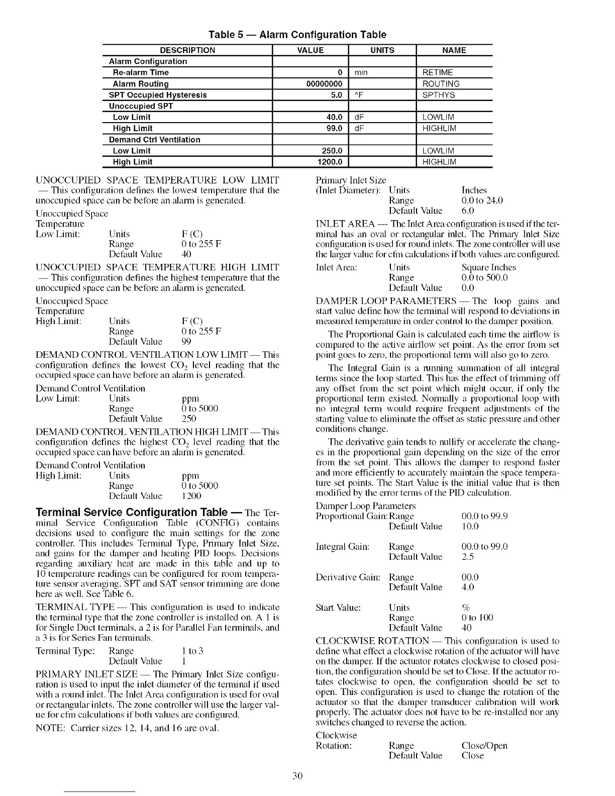
Table 5 -- Alarm Configuration Table
DESCRIPTION
Alarm Configuration
Re-alarm Time
Alarm Routing
SPT Occupied Hysteresis
Unoccupied SPT
Low Limit
High Limit
Demand Ctrl Ventilation
Low Limit
High Limit
VALUE UNITS NAME
0 min RETIME
00000000 ROUTING
5.0 "F SPTHYS
40.0 dF LOWLIM
99.0 dF HIGHLIM
250.0 LOWLIM
1200.0 HIGHLIM
UNOCCUPIED SPACE IEMPERATURE LOW LIMIT
-- This configuration defines the lowest temperature that the
unoccupied space can be before an tdarm is generated,
Unoccupied Space
Temperature
L_w Limit: Units F (C)
Range 0 to 255 F
Default Value 40
UNOCCUPIED SPACE TEMPERATURE HIGH LIMIT
-- This configuration defines the highest temperature that the
unoccupied space can be before an tdarm is generated,
Unoccupied Space
Temperature
High Limit: Units F (C)
Range 0 to 255 F
Default Value 99
DEMAND CONTROL VENTILATION LOW LIMIT -- This
configuration defines the lowest CO 2 level reading that the
occupied space can have before an tflarm is generated,
Demand Control Ventilation
L_w Limit: Units ppm
Range 0 to 5000
Default Value 250
DEMAND CONTROL VENTILATION HIGH LIMIT --This
configuration defines the highest CO s level reading that the
occupied space can have before an tflarm is generated,
Demand Control Ventilation
High Limit: Units ppm
Range 0 to 5000
Default Value 1200
Terminal Service Configuration Table -- The Ter-
minal Service Configuration Table (CONFIG) contains
decisions used to configure the main settings for the zone
controller. This includes Terminal Type, Primary Inlet Size,
and gains for the damper and heating PID loops. Decisions
regarding auxiliary heat am made in this table and up to
10 temperature readings can be configured for l_)om tempera-
ture sensor averaging. SPT and SAT sensor trimming am done
hem as well. See Table 6.
TERMINAL TYPE -- This configuration is used to indicate
the terminal type that the zone controller is installed on. A 1 is
for Single Duct termimfls, a 2 is for Partdlel Fan terminals, and
a 3 is for Series Fan terminals.
Terminal Type: Range 1 to 3
Default Value 1
PRIMARY INLET SIZE -- The Primtu'y Inlet Size configu-
ration is used to input the inlet diameter of the terminal if used
with a round inlet. The Inlet Area configuration is used for oval
or lectangular inlets. The zone controller will use the larger val-
ue for cfin calculations if both values are configured.
NOTE: Carrier sizes 12, 14, and 16 are oval.
Primary Inlet Size
(Inlet Diameter): Units Inches
Range 0.0 to 24.0
Default Value 6.0
INLET AREA -- The Inlet Area configuration is used if the ter-
minal has tm ovid or mctanguku" inlet. The Primtuy Inlet Size
configuration is used for l_)und inlets. The zone controller will use
the kuger vtflue for cfin calculations if both values am configured.
Inlet Area: Units Squtu'e Inches
Range 0.0 to 500.0
Default Value 0.0
DAMPER LOOP PARAMETERS -- The loop gains and
start value define how the temiinal will respond to deviations in
measured temperature in order contl_)l to the damper position.
The Proportional Gain is calculated each time the ailt]ow is
compared to the active airflow set point. As the enor fi__)m set
point goes to zero, file proportional temi will also go to zero.
The Integral Gain is a running summation of all integral
terms since the loop sttu-ted. This has file effect of trimming off
any offset from file set point which might occur, if only the
proportional term existed. Normally a propollional loop with
no integral term would require frequent adjustments of the
starting value to eliminate the offset as static pressure and other
conditions change.
The derivative gain tends to nullify or accelerate the chang-
es in the pl_)pollional gain depending on the size of the enor
from the set point. This allows the damper to respond faster
and morn efficiently to accurately maintain the space tempera-
ture set points. The Start Value is the initial value that is then
modified by the error terms of the PID c_dculation.
Damper Loop Partuneters
Proportional Gain: Range 00.0 to 99.9
Default Value 10.0
Integral Gain: Range 00,0 to 99,0
Default Value 2,5
Derivative Gain: Range 00.0
Default Value 4,0
Start Value: Units %
Range 0 to 100
Default Value 40
CLOCKWISE ROTATION -- This configuration is used to
define what effect a clockwise rotation of the actuator will have
on the &Lmpel: If the actuator rotates clockwise to closed posi-
tion, the configuration should be set to Close. If the actuator ro-
tates clockwise to open, file configuration should be set to
open. This configuration is used to change the rotation of the
actuator so that the &tmper transducer calibmfion will work
properly. The actuator does not have to be m-insttflled nor tiny
switches changed to reverse the action.
Clockwise
Rotation: Range Close/Open
Default Value Close
3O
 Loading...


