40MULA: Installation Instructions
Manufacturer reserves the right to change, at any time, specifications and designs without notice and without obligations.
12
Adapter(s) Installation When Coil Hangs Over the
Furnace
NOTE: On upflow installations where the indoor coil is placed in an
unconditioned space, a 6” wide piece of insulation should be
applied and wrapped around the outside of coil casing and
supply duct contact point.
NOTE: Consult the furnace installation instructions for any special
requirements when installing the coil to the furnace.
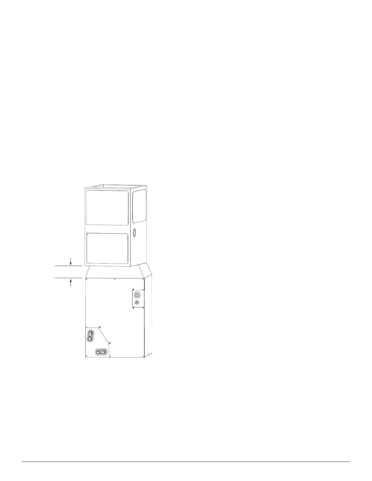
Downflow Coil Installation
IMPORTANT: Installing “A” coils rotated 90 degrees from
the front of the furnace in downflow applications can cause
water blow off or coil freeze up. This is due to the
concentration of air on one coil slab or lack of air on the
opposite coil slab. If the airflow is high due to ductwork or
other causes, and there is a chance for water blow off it is
recommended that a 4-in. minimum field supplied adapter be
placed between the coil and the furnace to allow the air to
distribute evenly to both coil slabs.
Fig. 10 — Downflow Installation with Coil Rotated 90
Degrees
5. Set cased coil on supply duct opening.
6. Place field fabricated 4-in. minimum adapter on coil casing. Adapter
should be tapered to fit coil/furnace combination when one of them is
larger than the other.
7. Set furnace on adapter.
NOTE: In downflow installation with a 4-way multipurpose furnace,
break off perforated duct flanges into the furnace (see the
furnace installation instructions for details).
Horizontal Coil Installation
The unit can be installed on a work platform, secured to roof truss in the
attic, suspended from hangers on the floor joists in crawl space, or
installed on blocks. It is designed to allow airflow in either direction, to
mate with horizontal-left or horizontal-right furnace installations. Ensure
the coil cabinet is level side to side and front to back.
It is allowable to add up to 1/2-in. additional slope over length and depth
of coil cabinet in the direction of drain pan connection.
Horizontal Right Installation
1. Use a field fabricated attachment plates to the secure coil to the furnace.
2. Use self-tapping screws to mount attachment plates to coil casing.
3. Connect furnace snugly against coil casing.
4. Use self-tapping screws to attach furnace.
5. Seal joint between coil casing and furnace to create an air tight seal
using locally approved materials.
6. Use cork tape to create air seal between the undersides of the pan
extension and front of the vertical drain pan as shown below.
7. Install included condensate pan extension and two corner screws.
8. If coil is wider than furnace, use 4-in minimum transition and self
tapping screws to attach furnace.
Horizontal Left Installation
1. Unbend the 4 tabs at the right side of the casing.
2. Connect the furnace snugly against the coil casing.
3. Use self-tapping screws to attach the furnace.
4. Seal the joint between coil casing and furnace to create air tight seal
using locally approved materials.
5. If the coil is wider than the furnace, use a 4-in. minimum transition and
self tapping screws to attach the furnace.
 Loading...