40MULA: Installation Instructions
Manufacturer reserves the right to change, at any time, specifications and designs without notice and without obligations.
13
Refrigerant Line Connections
NOTE: Factory nitrogen charge may escape past rubber plugs
during storage. This does not indicate a leaking coil nor
warrant return of the coil. Size and install refrigerant lines
according to information provided with outdoor unit. Coil
connection tube sizes are shown in Table3. Route refrigerant
lines to the coil in a manner that will not obstruct service
access to the unit or removal of the filter. Do not use damaged,
dirty, or contaminated tubing because it may plug refrigerant
low-control device. ALWAYS evacuate the coil and field-
supplied tubing before opening outdoor unit service valves.
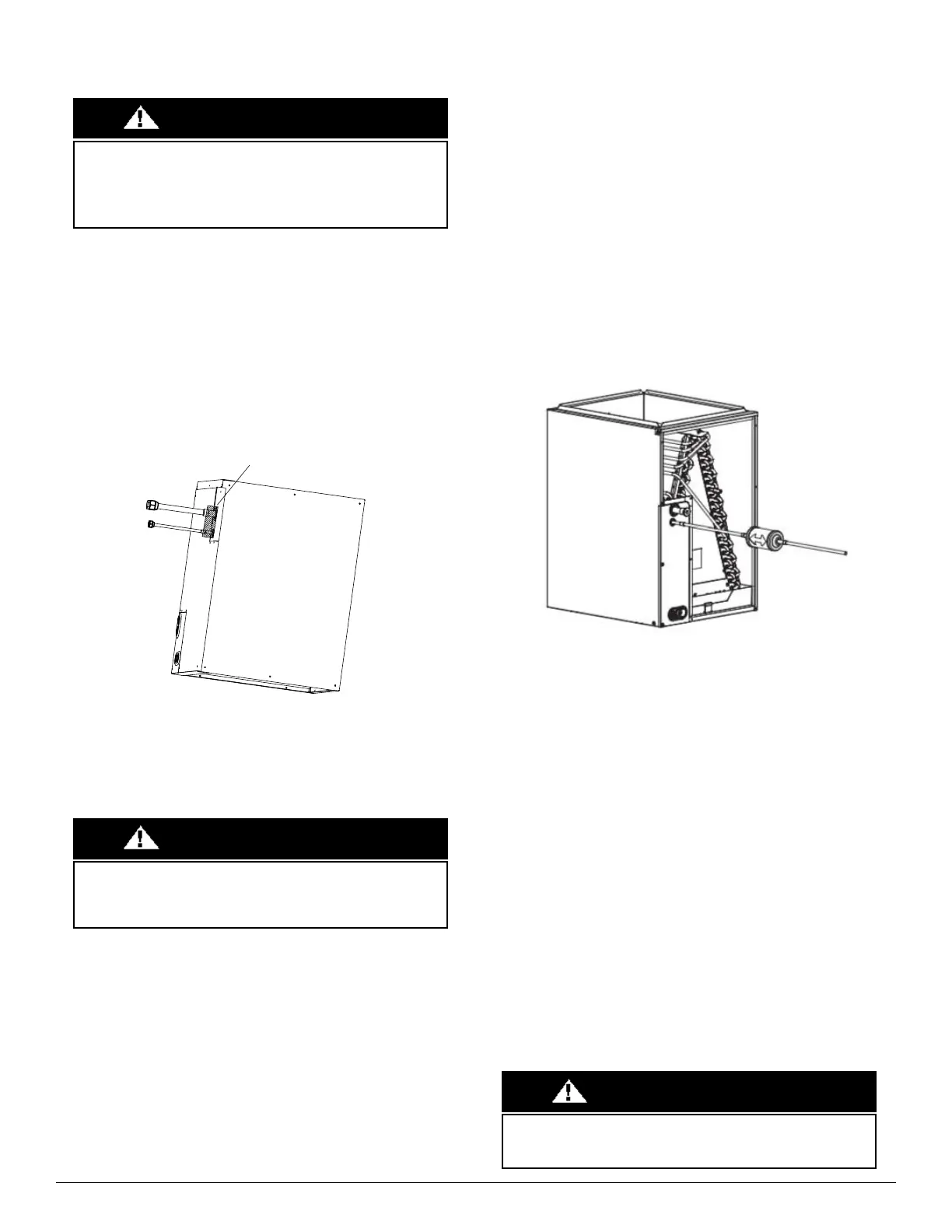
Fig. 11 — Weld the Pipe
Connect Refrigerant, Liquid, and Suction Lines
For matched systems, use line sizes recommended in the outdoor unit’s
Installation Instructions.
NOTE: For the coils (models 40MULAQ24XAX, 40MULAQ36XBX,
40MULAQ24XBX, 40MULAQ36XCX, 40MULAQ48XCX,
40MULAQ60XDX) that do not have a serviceable service
door. If the cabinet door is removed for that coil prior to
brazing, it cannot be installed after brazing is complete. Make
sure that the cabinet door is installed prior to brazing for the
above stated coils model numbers.
The coil can be connected to outdoor units using field-supplied tubing of
refrigerant grade ALWAYS evacuate the tubing and reclaim the
refrigerant when making connections or flaring the tubing. Leak check
connections before insulating entire suction line.
1. Remove the cabinet access door.
2. Remove the rubber plugs, the suction plug then the liquid plug, from
the coil stubs using a pulling and twisting motion. Hold coil stubs
steady to avoid bending or distorting.
3. Remove the tubing plate with rubber grommets and slide plate with
grommets onto the refrigerant lines (field line-set), away from the braze
joints.
4. Filter Drier (Heat Pump Drier ONLY)
a. Cut a minimum 4" length of 3/8 tubing and assemble:
•3/8” adapter
•short tubing
•filter drier
•lineset
b. Wrap filter drier with damp cloth.
c. Flow nitrogen.
d. Braze assembled components from Step 1 above.
Fig. 12 — Filter Drier Components
The filter drier must be replaced whenever the refrigeration system is
exposed to the atmosphere. Only use factory specified liquid-line filter
driers with rated working pressures less than 600 psig.
NOTE: DO NOT install a suction-line filter drier in liquid line.
5. Fit the refrigerant lines into the coil stubs. Wrap a heat sinking material
such as a wet cloth behind braze joints.
6. Wrap TXV and nearby tubing with a heat-sinking material such as a
wet cloth.
7. Use 1/2 psig Nitrogen purge in the suction and out the liquid line.
8. Braze using a Sil-Fos or Phos-copper alloy. Do not use a soft solder.
9. After brazing, allow the joints to cool. Carefully remove the TXV bulb
insulation and verify that the TXV bulb is securely fastened with a hose
clamp. Tighten the screw a half-turn past hand tight with TXV bulb
placed in the indentation with full contact with the vapor line tube. Re-
wrap the TXV bulb with insulation.
10. Leak check the connections before insulating the entire suction line.
11. Slide the tubing plate with rubber grommets over joints. Position the
tubing at the center of each grommet to ensure an air seal around the
tube. Reinstall the cabinet door.
Failure to follow this warning could result in personal injury. Wear eye
protection. Coil is factory charged with 15 psi nitrogen.
The coil is under pressure and the TXV screen is in place behind the liquid
line plug. DO NOT remove liquid line plug first, always remove the
suction line plug first to de-pressurize the coil.
WA RNING
Cover with a wet towel when welding the pipe.
Failure to follow this caution may result in property damage. Take
precautions to ensure the Aluminum tubes do not come in direct contact or
allow for condensate run to with a dissimilar metal.
Dissimilar metals can cause galvanic corrosion and possible premature failure.
CAUTION
Failure to follow this caution may result in product damage.
To avoid valve damage to the refrigerant control device while brazing,
valves must be wrapped with a heat-sinking material such as a wet cloth.
CAUTION
 Loading...