25
REFRIGERANT LINES
General refrigerant line sizing:
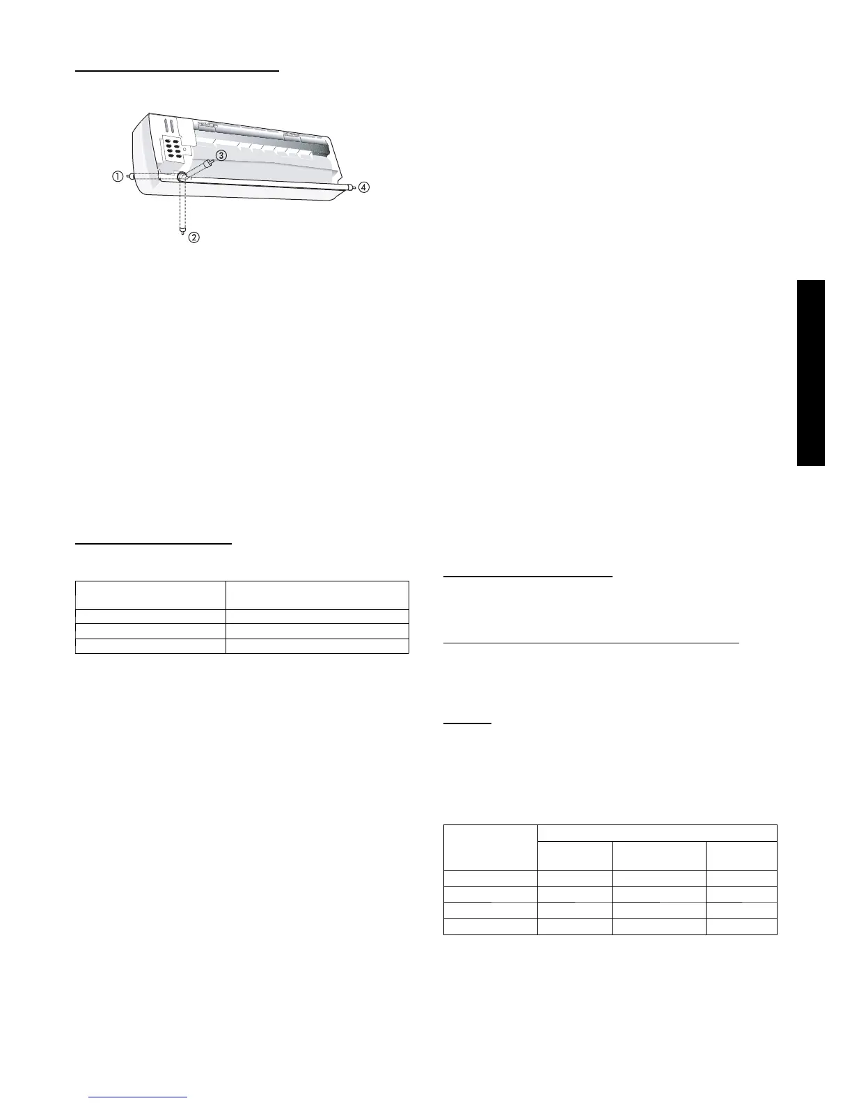
1. Piping for indoor unit can be routed in the direction shown
in Fig. 12.
A08358A
Fig. 12 – Indoor Unit Piping Configurations
2. Refrigerant lines should not be buried in the ground. If it is
necessary to bury the lines, not more than 36--in (914 mm)
should be buried. Provide a minimum 6--in (152 mm)
vertical rise to the service valves to prevent refrigerant
migration.
3. Both lines must be insulated. Use a minimum of 1/2--in.
(12.7 mm) thick insulation. Closed--cell insulation is
recommended in all long--line applications.
4. Special consideration should be given to isolating
interconnecting tubing from the building structure. Isolate
the tubing so that vibration or noise is not transmitted into
the structure.
NOTE: Since the same outdoor unit can be matched with
different types of indoor units, it may not have enough
refrigerant charge. Refer to the Physical Data tables to
determine if additional charge is required.
Long Line Applications
The following table indicates the maximum line lengths that can be
used with the high wall systems.
ITEM
MAX LENGTH ALLOWED
ft (m)
Total Piping 200 (61)
Max Lift (Fan Coil above) 65 (20)
Max Drop (Fan Coil below) 200 (61)
For line lengths over 25 ft (7.6 m), .3 oz of charge should be added
for each additional foot up to the maximum allowed.
For line lengths over 80 ft (24.4 m), certain accessories and
adjustments to the piston sizes are also required.
Refer to the Duct--Free Split Systems Long Line Guide for
additional information.
CONTROL SYSTEM
The 40QNC,QNQ unit is equipped with a microprocessor controls
to operate the system and provide optimum levels of comfort and
operating efficiency.
The main microprocessor is located in the control box of the fan
coil unit with thermistors located in the fan coil inlet and on the
indoor coil. These thermistors monitor the system operation and
control the operating mode. To change the settings or the modes of
operation, use the factory supplied wireless remote control or
accessory wired controller or Zone Manager.
The 40QNC,QNQ unit has 5 operating modes:
S Fan Only
S Auto (heat pump models only)
S Heating (heat pump models only)
S Cooling
S Dehumidification (Dry)
FAN ONLY -- In Fan Only mode, the system filters and circulates
the room air without changing the room air temperature.
AUTO -- In Auto mode, the system will automatically select one of
the following operating modes: cooling, heating or fan only based
on the difference between the room temperature and the set point
temperature.
HEATING -- In the Heating mode, the system heats and filters
room air.
COOLING -- In Cooling mode, the system cools, dries and filters
room air.
DEHUMIDIFICATION (DRY) -- in Dehumidification (Dry)
mode, the system dries, filters and slightly cools room temperature.
This mode does not take the place of a dehumidifier.
In addition to the above modes that are selected by using the
remote control, The unit can run in two other modes selected by
the manual button:
S EMERGENCY RUN
S TEST MODE
EMERGENCY mode -- is used when the remote control is
misplaced or the batteries in the remote control have expired.
Pushing the manual button under the front cover will put the unit
in Auto mode with a predetermined set point (73.4_F/ 23_C) .
TEST mode -- is used when a technician needs to diagnose the
unit for a malfunction. The unit can be set into TEST mode using
the remote control. It will run regardless of the set point.
The microprocessor controls offer additional comfort and economy
features like SLEEP mode, TIMER and AUTO SWEEP. Refer to
the Owner’s Manual for additional details on these features.
USER INTERFACE
The units come standard with a wireless remote control. The
wireless remote has a range of 25 ft (8 m) when pointed toward the
unit.
For some applications (commercial), a wired remote may be more
desirable. A wired remote control is offered as an accessory.
For applications that have multiple units, these controls offer
additional flexibility
Two Units in Same Room
If the two units are working independently, the two remotes can be
configured differently so that the signal from one remote does not
interfere with the operation of the other units.
Multiple Units Controlled by One Controller
When there is an application where all units require the same
setting, up to 6 units can be daisy--chained and controlled by one
wired remote control. Total length of connecting wire can be up to
500 ft (150 m).
Zoning
For applications that require zoning, the Zone Manager is offered
as an accessory. This will allow up to 32 units to be connected in
up to 8 zones. Each zone can be programmed for 7 days with each
dayhaving4periods.
AIRTHROW DATA
Unit Size
Air Throw Data ft (m)
High
Speed
Medium
Speed
Low
Speed
018 35 (10.7) 30 (9.1) 25 (7.6)
024 35 (10.7) 30 (9.1) 25 (7.6)
030 40 (12.2) 35 (10.7) 27 (8.2)
036 50 (15.2) 40 (12.2) 30 (9.1)
4QNC,QNQ/38HDF,QRF
 Loading...


